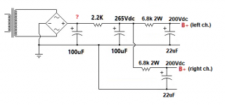
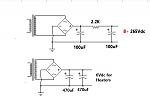
Sorry, I meant something like this (in the attached schematic).
__________________
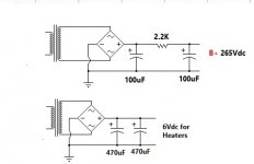
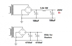
Or, you could take your circuit with the two 100uF capacitors and replace the 2.2k ohm resistor with a 5.6k ohm 5W resistor. But the one I drew will give you a much more quiet supply.
__________________
Or, you could take your circuit with the two 100uF capacitors and replace the 2.2k ohm resistor with a 5.6k ohm 5W resistor. But the one I drew will give you a much more quiet supply.
Attachments
Last edited:
Sure, that should work fine.
The thing to worry about is the wattage rating of the resistors you use.
If that 2.2k resistor is dropping 35V (let's say), then 35/2200 = 15.9mA (0.0159 A).
If you put a 5k resistor there, and it drops let's say 14mA (0.014 A) then
5000*0.014 = 70V, and you might get 230V B+. But that would be helpful (half of 230V is 115V, which is within spec for the 6DJ8s' plate-cathode voltage).
If the 10k ohm resistors in parallel drop 70V with 14mA across them, they'll be dissipating 1W altogether. So each resistor will be dissipating 1/2 a watt. Make sure each 10k resistor is rated for at least 1W, although 2W rated ones will be much better (they won't get so hot).
That will be a start. Not a cure. Just a start.
--
Last edited:
- Home
- Amplifiers
- Tubes / Valves
- modifing 6DJ8 kit for DAC output stage