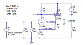
The drawing is for a "tube preamp kit" (Chinese made) that I bought of Ebay, I'm trying to use/modify it so it will work as an output stage for a AD1862 DAC, the AD1862 is a I out DAC with 2ma peak to peak output and I'm using a 150R resistor for the I/U conversion so I need high gain here.
I'm a newbie in tube circuits so any input/suggestion is highly appreciated🙂
I'm a newbie in tube circuits so any input/suggestion is highly appreciated🙂
Thanks.
So the signal coming off the DAC output is very tiny? About how many millivolts, do you think?
--
So the signal coming off the DAC output is very tiny? About how many millivolts, do you think?
--
Is that peak, or RMS?
If peak, that would be about 200mV RMS. (0.2V)
Isn't that about the normal nominal output level for line level sources? I see on most CD player specs that 200mV RMS is considered the nominal average signal level output. Peak level is quoted as 2V RMS for 0dBFS.
Does this need any gain at all?
I can understand the desire to add some 'tube warmth' to the sound, but you don't want to add so much gain that you also add noise, hum, distortion, etc.
I'm wondering if just a cathode follower on the output of the DAC is all you really need (no gain, just a tube buffer).
--
it's 0.3V peak, 2ma*150R= 0.3V
without that gain there is no sound output (or very,very,very little).
without that gain there is no sound output (or very,very,very little).
Unfortunately, that presents another problem.
The B+ supply in this circuit is 265V.
The full B+ is present at the plate of the cathode follower 6DJ8.
The voltage at the cathode of the cathode follower 6DJ8 is about 75V.
265 - 75 = 190V from plate to cathode.
The 6DJ8 (ECC88) has a maximum plate to cathode voltage rating of 130V (according to the Sylvania data sheet).
That 190V from cathode follower plate to cathode is far too much.
It's likely that any 6DJ8 or ECC88 used in this circuit will fail prematurely due to its maximum voltage spec being violated by that much.
--
Last edited:
The 6DJ8 (ECC88) has a maximum plate to cathode voltage rating of 130V (according to the Sylvania data sheet).
That 190V from cathode follower plate to cathode is far too much.
--
If I understand correctly I should add a plate resistor on the cathode follower, correct?
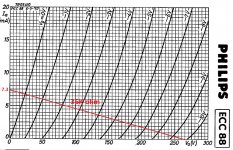
This is the first stage load line, 265Vdc/36K=7.3mA
On the 150R bias resistor I'm measuring 1.57Vdc, which means that there is a 10mA current flowing through it, which is way out of the load line.
Am I missing something?
Because that circuit 'stacks' the cathode follower load resistor on top of the first stage cathode resistor, that 150R resistor does see 10mA across it. But that's the plate currents of both the first stage and the second stage combined. So that's nothing to worry about, in and of itself.
--
If I understand correctly I should add a plate resistor on the cathode follower, correct?
Unfortunately, that won't solve the problem, and it would add other problems.
The problem is this circuit was not thought out well in the first place. It's in need of a complete re-thinking.
From what I've seen, this is the problem with these cheap Chinese tube preamps you see on eBay and Aliexpress, etc. Many are not competently designed, and some are really bad.
Sorry. I don't like to be the bearer of bad news like that.
--
PS - Is the B+ really 265V? Maybe if you could drop that down to 250V...
Last edited:
Sorry. I don't like to be the bearer of bad news like that.
--
You are not at all, the other way around, you're helping me understanding better and I appreciate it a lot.
That's the reason I've opened this thread from the first place, to understand how I can modify this circuit for my needs....and learn about it.
Thank you.
PS - Is the B+ really 265V? Maybe if you could drop that down to 250V...
It's actually 300Vdc but drops to 265Vdc once I connect it to the circuit.
What is the purpose of the 15K resistor (R5) ?
Can't it drop the voltage on the cathode if I'll change it's value?
Can't it drop the voltage on the cathode if I'll change it's value?
Last edited:
It's actually 300Vdc but drops to 265Vdc once I connect it to the circuit.
That's to be expected, and tells us that the B+ power supply is not regulated. When the tubes draw current, the voltage from the B+ supply drops.
The first stage and second stage are direct coupled ("DC coupled"). The plate of the first stage is directly connected to the grid of the second stage.
If you change the value of the 2nd stage cathode resistor, it won't change the 2nd stage plate to cathode voltage by very much. Certainly not by the 60V you need. Even so, you don't want to run the 6DJ8s with 130V on their plates. That's the maximum, and is not where they'll perform well. 100V on the plate would be much better for 6DJ8.
It would be helpful to drop that 265V B+ under load down to about 200V. That way we could get 100V on the plate of the first stage, and about 102V or so at the cathode of the second stage.
If the two stages draw 10mA (0.01A), then we can figure out the resistor value needed to drop 65V at 10mA, using good old Ohm's Law.
65/0.01 = 6,500 ohms.
We could choose 6.8k, which is a standard value.
If that single 6.8k resistor has 10mA drawn across it, it will drop 68V. What will be the power dissipated in that resistor? That's basically I(A).
0.01(68) = 0.68 watts.
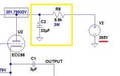
I'd choose a 3W metal oxide resistor. Those are commonly available.
You can use that to increase the power supply 'filtering' (decoupling). You'd use 1/2piFR to figure out what value capacitor to choose to filter down to about 1Hz (the usual target), but you can also cheat and divide the value of the resistor into 150,000 to get the capacitance in microfarads.
150,000/6,800 = 22.06
We can use a 22uF 350V capacitor (or 400V if that's more available). A 10uF cap would probably work just as well in this instance. If 10uF 400V is easier to get a hold of, then by all means use that. However, I wouldn't go crazy and add really high values of capacitance here like 100uF or 220uF. That could cause high current draw at power-up, blowing things elsewhere.
The 6.8k 3W resistor goes in series with the B+, and the 22uF 350V capacitor goes from the B+ supply to ground. I've attached a snippet to illustrate this. It's R8 and C2 in that snippet.
You will need two of these decoupling networks, one for each channel (one decoupling network for each 6DJ8 tube).
Attachments
Last edited:
That's to be expected, and tells us that the B+ power supply is not regulated. When the tubes draw current, the voltage from the B+ supply drops.
Thanks for the detailed exlanation.
There are 2 paralelled 100uF and 2.2K resistor in between on the power supply output.
I have another 150Vdc power supply that I can use instead of this one but I'll need to change the whole circuit components values accordingly.
Thanks for the detailed exlanation.
There are 2 paralelled 100uF and 2.2K resistor in between on the power supply output.
If I understand you correctly, you could replace the 2.2k resistor with a larger value to bring the 265V down to 200V.
Also, two 100uF in parallel equals 200uF, which is a lot of capacitance to charge up at power-on. Be careful of stressing the power transformer and rectifier diodes with a turn-on current spike.
I have another 150Vdc power supply that I can use instead of this one but I'll need to change the whole circuit components values accordingly.
You could redesign the circuit to work from a 150V supply. Aim for 75V on the plate of U1 and a couple volts above that on the cathode of U2.
--
Using 1 100uF capacitor and 6.8K resistor (resistor before capacitor) the voltage dropped to 160Vdc.
When the resistor is after the capacitor the voltage is 210Vdc.
When the resistor is after the capacitor the voltage is 210Vdc.
Last edited:
Did you have both channels fed by that 6.8k/100uF filter? If so, that would explain it. As I wrote in the post, you want 6.8k for each channel. If you use one RC for both channels, use 3.3k and 100uF. That should get you close to 200V.
The resistor should be placed as shown in the accompanying drawing.
The resistor should be placed as shown in the accompanying drawing.
Attachments

Last edited:
- Home
- Amplifiers
- Tubes / Valves
- modifing 6DJ8 kit for DAC output stage