It's been opened to verify the internals are all there. Seems it may have been intended to be a cutaway engine! A friend of mine was even so kind as to make the drive and measure the stator etc to ensure they're within spec. Will still be needing a proper once-over, but that's something I do with any new bike purchase anyways.
I'll make sure to sneak in some minor bike updates for those who may be interested in here 😊
I'll make sure to sneak in some minor bike updates for those who may be interested in here 😊

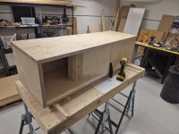
Progress is being made! Using the plywood base to build a fixture, so the second speaker should go together a bit faster.
Still undecided as to the final finish and whether or not to try and minimize externally visible screws/dowels. I have a domino cutter which I'll be using to some extent, but I feel like screws must be infinitely better with regards to holding two panels together. Feel free to enlighten me!

Still undecided as to the final finish and whether or not to try and minimize externally visible screws/dowels. I have a domino cutter which I'll be using to some extent, but I feel like screws must be infinitely better with regards to holding two panels together. Feel free to enlighten me!
Makes sense! So realistically I should be fine so long as I clamp things down properly.
Another thing: Due to stock limitations, the side panels of each speaker will have front facing "endgrain" running along each side. This detail - coupled with the boring figuring of birch ply - is mainly why I'm considering painting the cabinets when finished. One of my primary aims is to not make too much work for myself -- But does anyone have any creative ideas as to making this look decent?
I've been considering painting everything but the baffle and running some sort of veneer down along the upper horn mouth, curving around just out of sight. Will be mocking it up in Fusion tomorrow, but I'm open to any other ideas!
Screws actually weaken a joint, ergo more is ideally required till you wind up with a rivet pattern, so where strength is required, remove clamping screws after joint has dried and glue in dowels.
Gotcha. Will have to give it a bit more thought.
On another subject -- I rendered some different versions of the D2 and this is the one I've liked the most so far:

Never mind the dots on the side, that's just the ends of the tension rods poking out. Heading to the workshop tomorrow to get some work done, will keep ya posted.
On another subject -- I rendered some different versions of the D2 and this is the one I've liked the most so far:
Never mind the dots on the side, that's just the ends of the tension rods poking out. Heading to the workshop tomorrow to get some work done, will keep ya posted.
So! After a weekend-long buildathon, I'm not much farther ahead than I was as of my last update...
I cut all the panels out, and had them taped up.

-- Then I noticed that I'd cut the rear panel 10cm short.
Will ultimately have to extend it using one of the leftover pieces, since I don't have stock enough to cut whole a new one. Fortunately the rear panel for the other speaker was the right length so I just used that for now.
Took the opportunity to increase the dimensional accuracy of everything since I'd have to remake most of the fixture anyways. Now I'm pretty much back where I was, but things are accurate to <1mm and I have a lot of the panels screwed together.

It's slow going and I'm already tired of these things, but I'm going to keep hacking away at em so I at least have the shells put together before the end of the month.
I cut all the panels out, and had them taped up.
-- Then I noticed that I'd cut the rear panel 10cm short.
Will ultimately have to extend it using one of the leftover pieces, since I don't have stock enough to cut whole a new one. Fortunately the rear panel for the other speaker was the right length so I just used that for now.
Took the opportunity to increase the dimensional accuracy of everything since I'd have to remake most of the fixture anyways. Now I'm pretty much back where I was, but things are accurate to <1mm and I have a lot of the panels screwed together.
It's slow going and I'm already tired of these things, but I'm going to keep hacking away at em so I at least have the shells put together before the end of the month.
Things are chugging along! Fixed some minor SNAFUs and profiled the inner corner of the first horn section so my printed jig fits.

Now I'm at the point where the glue-up is getting real close, and to be honest I have no clue how to go about it. Screws, glue and biscuits, sure -- But what do I do to seal any minor inconsistencies in panel width etc?
For example, some of the panels are ~0.5mm short (width-wise) in parts. This is due to having to stop while cutting some panels.
I intend to seal most of the seams with some sort of silicone caulking or other, but one of the sides won't be able to recieve this treatment as I naturally won't be able to reach certain sections.
Can I count on the glue taking up the extra space, or should I maybe use some of that glue that foams up?
I use(d) Mortite rope caulk. My limited experience with expansion foam is that it was too rigid and didn't stick well, so maybe fine for your static indoor app, but no good for sealing even minor gaps in exterior house siding/roof/whatever. Re glue, guess if you can keep it in the gap it should be fine.
Last edited:
Ok. So you didn't really bother with glue on the one side at all? Just Mortite and screws/dowels? What about something like Butyl?
Last edited:
Things are chugging along!
Haven't had much time to work on the speakers lately, but some of the internals are properly screwed together and aligned, braces laser cut, and side panels roughly cut.
The glue-up is getting closer, and I'm not quite sure how to go about some of the shallower angles. I'm sure I'll figure it out.
Stay tuned!
Nice work, Jmartell!
My one comment after having built many horns and TL’s with folded paths is that the structure is extremely stiff due to all the natural bracing provided by the many internal passages. You can use much thinner wood like 9mm thick ply and it will still be quite strong and much lighter weight, saves money and time, and provides more internal volume taken up by the thickness of the wood to allow for an overall more compact cabinet. You can keep the front baffle thicker 18mm ply because you need rebates and more wood to mount a driver. But there is no need for internal channels or side walls to be so thick.
I have even used 5mm paper faced foam core with a lot of success for prototypes as everyone knows by now. 🙂
While on the subject; If you guys need help with anything CAD-related I'd be happy to help. Least i can do for all your advice.
- I do a lot of 3D printing, would there be some way to apply this to the speakers? For example placing vortex generators, diffractory geometry or stepped panels to break up HF along some part of the internal geometry. Maybe in the filter chamber? Figure I have access to so much modern tech, why not use it.
Very curious to learn if you had any luck with the vortex generator or diffracting geometry exploration?
Nice work, Jmartell!
My one comment after having built many horns and TL’s with folded paths is that the structure is extremely stiff due to all the natural bracing provided by the many internal passages. You can use much thinner wood like 9mm thick ply and it will still be quite strong and much lighter weight, saves money and time, and provides more internal volume taken up by the thickness of the wood to allow for an overall more compact cabinet. You can keep the front baffle thicker 18mm ply because you need rebates and more wood to mount a driver. But there is no need for internal channels or side walls to be so thick.
I have even used 5mm paper faced foam core with a lot of success for prototypes as everyone knows by now. 🙂
Stands to reason. I figured I might as well go overboard on the rigidity and weight to prevent my my lack of skill from coming into the equation and messing things up 💩
Since people didn't seem all too enthusiastic about the idea I figured it wouldn't have an effect significant enough to warrant putting the time in. That said it's still something that could be messed around with after the speakers are built, so if I find the time I may yet get around to it.Very curious to learn if you had any luck with the vortex generator or diffracting geometry exploration?
Work has been done. All of the "tracks" for the braces are done, and I've glued in the first few.

Spent a good few hours wasting material in the laser cutter trying to get the fit of the braces perfect, not quite there yet but it's looking good.

Now the entire middle section is glued up, so this week I'll be continuing along that line!
Spent a good few hours wasting material in the laser cutter trying to get the fit of the braces perfect, not quite there yet but it's looking good.
Now the entire middle section is glued up, so this week I'll be continuing along that line!
... And for those interested, I brought the turbo engine home about a month ago -- It's immaculate.

Things are progressing rapidly! All of the braces are glued in (on one side) and only one glue joint remains for the primary horn profile.
Now we're at this point in the build, I have some questions regarding the driver placement.
Firstly, would the Dallas 2 horns benefit from an offset driver placement?
And secondly, the mounting depth of the Beta-8's is specified as being 10mm -- this would roughly put the large rubber "lip" flush with the face of the baffle. Would diffraction be helped if the resulting "trench" between the rubber lip and cutout was filled?
Attachments
- Home
- Loudspeakers
- Full Range
- Modified Beta 8 BLH Design? Help!