I recently purchased a Velleman K4040 amp which I have wanted for quite some time. It was assembled by an engineer a few months ago from a kit that had been in storage for several years and appears to be well built. It came with Electro Harmonix EL34’s. Looking around, it seems that, while being a good amp, it has some shortcomings and can be modded to make it much better. Being a retired electronics tech and an avid audiophile I want to make it the “best it can be” without a complete redesign. It seems there are some mods that can be done such as replacing the 12au7 tubes with 12ax7’s, replacing the concertina phase splitter with a schmidt using 12at7’s ( https://www.diyaudio.com/community/...man-k4040-tube-amp-owner.383508/#post-6952838 ), replacing the coupling cap’s with 100nF’s, etc.. I would also like to replace the EL34’s with KT88’s but still operate them in class AB1 ultra-linear ( https://blog.easychipamp.com/2020/12/velleman-k4040-tube-amplifier.html ), unlike the Velleman K8010’s KT88 bias of 75ma. I must thank Baudouin0, alexcp, ironradio, arcorob, & others for their excellent posts on the subject. This leaves some questions………. In their K8010, Velleman chose to use 47 ohm cathode resistors for their K88’s while the K4040 uses 10 ohm and ironradio chose to use 6.7 ohm with his KT88 mod. I think I understand why to use 6.7’s if you want to bias for 60ma and use the led indicator as is. Is there an optimum cathode resistor value if a person wanted to adjust bias using a meter and not use the led indicator? Also the screen feed resistor value is something I don’t understand. Velleman uses 180 ohm in the 4040 but I’ve seen recommendations of 480, 800 and 1K. Is there an “optimum” value & does it depend on whether the output tubes are EL34’s, 6L6’s or KT88’s? What would be best for KT88’s? Also I noticed that Velleman chose to use DC for the heater of the 12AU7 in the 8010. Why did they do this? Any help or suggestions would be very much appreciated.
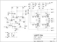
https://www.diyaudio.com/community/attachments/manual_k4040-pdf.1028988/
https://www.velleman.eu/downloads/0/manual_k8010.pdf
https://www.diyaudio.com/community/attachments/manual_k4040-pdf.1028988/
https://www.velleman.eu/downloads/0/manual_k8010.pdf
Last edited:
The screen resistor is ideally zero, but primarily serves a fuse to protect the transformer screen winding.
So the actual resistance and wattage are a matter of judgement. Values used range from 100R to 1k.
So the actual resistance and wattage are a matter of judgement. Values used range from 100R to 1k.
Thanks for your reply, rayma.
No other K4040 modders out there? There used to be a fair amount of interest but I guess that was a few years ago. 🙁
No other K4040 modders out there? There used to be a fair amount of interest but I guess that was a few years ago. 🙁
Also I noticed that Velleman chose to use DC for the heater of the 12AU7 in the 8010. Why did they do this?
There should be less hum with DC for the input tube filament.
Thanks, I think I will add that to my proposed mod list.There should be less hum with DC for the input tube filament.

I got a reply from Benny and he basically told me that he had three mod levels for the K4040......
Basic = driver and input stage and better components
Advanced = new driver stage with interstage transformer
Final = New output transformers
His mods are commercial...........which is understandable.
Basic = driver and input stage and better components
Advanced = new driver stage with interstage transformer
Final = New output transformers
His mods are commercial...........which is understandable.
I used to have a K4040 it was my first kit and is a good teaching platform. The input tube did need DC to stop hum from the speakers. It has just a 12K from cathode to ground allowing hum to get coupled from the heaters. You can use KT77 on the output tubes as it blows EL34's like lamp bulbs. Don't swap the cathode resistors out they are meant to blow. The KT88/6550 works better with output power but takes more heater current and requires a small change to get more negative bias. Yes the driver stage needs a revamp its quite rubbish. Try putting in 10KHz sinewave in and you get a triangle out! The mains transformer is very up to the job. The output transformers are good at the bass end but do start to get appreciable phase lag at HF which makes the NFB a little difficult - always use the 4R tap for the NFB.
There's lots of mods for the K4040 on diyaudio if you search.
There's lots of mods for the K4040 on diyaudio if you search.
Thanks for your post, baudouin0. I have read all your posts on modding your K4040 and they have helped me understand a lot on the subject. I do plan on using KT88's and want to use much of Ecdesigns mod, replacing the 12AU7 with a 12AX7 and using his schmidt phase splitter using 12AT7's with the necessary circuit changes of course. I also think that I want to incorporate Velleman's DC heater supply for the preamp tube that they decided to use in the K8010 & 8011. I read somewhere that using a spiral-wound filiament 12AX7 and keeping the AC supply would work too. Which would be better? I'm still accumulating needed parts & info and want to continue listening to it until I have everything I need. Thanks for any comments or info.. 🙂

I wouldn't increase the coupling capacitors, as it might result in motorboating.
And there aren't »spiral wound« 12AX7's. You might search for genuine 7025's or European ECC83's, as both featured bifilar heaters for increased hum rejection.
Best regards!
And there aren't »spiral wound« 12AX7's. You might search for genuine 7025's or European ECC83's, as both featured bifilar heaters for increased hum rejection.
Best regards!
I was planning on using 100nF coupling cap's instead of the 22nF that Velleman used in the K4040. I believe that is the value that Ecdesigns used. Velleman chose to use 68nF in the K8010 & K8011. I read that it was to increase bass response. I'll be on the lookout for motorboating and appreciate the caution though.
Like Kay says some things are right and some are wrong. I used DC for the first heater and that worked but there are other solutions. Increasing the coupling caps may well cause a LF peak at 1Hz before motorboating occurs. Actually because of the NFB changing caps does not always increase bass. I find the first step is an accurate simulation of the amp including the OPT. Its a shame there's no PCB drop in replacement for the first and driver stages.
You make a comment about screen resistors. The increase in values was to reduce screen current and stop the EL34's popping. For KT88 that won't happen so you can use 220R 180R its not critical.
Certainly using a 12ax7 as a driver is weak and is only really suitable for guitar amps when the top end is not needed. 12au7, 12at12, e88cc would be a much better choice at higher current.
Certainly using a 12ax7 as a driver is weak and is only really suitable for guitar amps when the top end is not needed. 12au7, 12at12, e88cc would be a much better choice at higher current.
You made a comment, "The KT88/6550 works better with output power but takes more heater current and requires a small change to get more negative bias."
The 6.3V secondaries are capable of supplying the needed extra current, aren't they? What small change do you suggest to get more negative bias?
Also, for KT88 use, should the cathode resistors stay at 10 ohm or is their a better value? I realize that changing them would require using a meter to set the bias as the led method would be wrong. Of course if I wanted to bias @ 50ma, couldn't I use 8 ohm 1W cathode resistors which would give me .4V @ cathodes for correct led indication @ 50ma bias? Also, thanks to Kay for his comments.
I had no issue with 8x6550A's and to power transformer did not get hot. If you want to have 50ma then reduce the 10R to get .4V. Of course you are also increasing the load on the power transformer.
Mods to the amp are here:
https://blog.easychipamp.com/2020/12/velleman-k4040-tube-amplifier.html
I've not simulated the mods.
To get the negative rail more negative R5, R10 = 10K from 22K. The mods add a zener on the negative rail so this will need to change too. If you use 6550A/KT88 I would put screen resistors back to say 220R otherwise you will loss some of the benefits of increased output power.
There's also some advantage in upping the HT reservoir caps to decrease 100Hz intermodulation. I think you can get bigger ones that will fit on the PCB with longer life.
Yes, the mods @ easychipoamp are the ones that I was planning on doing along with changing C39-C42 to 470uF/450v and C37, C38 to 220uF/450v, R5, R10 to 10k and 100nF across D23. I think I will keep the 10 ohm cathode resistors and bias @ 40ma initially and maybe experiment at a slightly higher setting later (?). Of course the coupling caps are shown as being 100nF which I assume (and hope) don't cause the LF peak at 1k and motorboating that you and Kay mention. Those are the ones that I have on order. I also want to use the global feedback to V11's cathodes. Is there any way you might find time to simulate the complete mod sometime? I know this is asking a lot.... 🙄 Thanks for all the help!
Attachments
The KT88 heater current demand of 1.6 A vs. 1.5 A per each EL34 really isn't of any concern. But if you're planning to substitute your EL34's with KT88, please obey the maximum grid leak value which is smaller than with EL34's. Hence, you'll indeed need bigger coupling capacitors between the PI and the finals.
Best regards!
Best regards!
- Home
- Amplifiers
- Tubes / Valves
- Modding a Velleman K4040