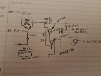
This IC (if used the same way as the 5470 in the Fusion) uses a single-ended supply and will be biased to 1/2 of the supply voltage feeding it.
I tested supply pin13 and bias output voltages pin11 and pin14 on the pwm controller when the supply voltage is at 13.7v the bias outputs are at .5v DC. Now if I back down supply voltage to 8 v on pin 13 my bias outputs has 3.71v pin 11 and 14
For every pin you mention, you need to also state which component that it's on.
What are you referring to as 'bias'?
Having only your diagram, it appears that the regulator is fed by a combination of B+, through the rectifiers which gets additional voltage from the winding that you have drawn.
What are you referring to as 'bias'?
Having only your diagram, it appears that the regulator is fed by a combination of B+, through the rectifiers which gets additional voltage from the winding that you have drawn.
Ok so I looked at the data sheet for u1 the tlc2274c it has a differential power input -8v to+8v so the 14.8v input was in spec. I replaced u1 and the voltage regulator. The amp will play now and the gain and freq knobs are smooth with no glitches. When you hook power up to the amp the protect light is on and will not turn on with the remote. If you leave the remote wire hooked up and power cycle the power input the amp will turn on and play with the protect light off. Any suggestions. I did notice one of the power supply toroids is making a whining noise and is being played through the speaker outputs but not that loud
So I read all of the other posts you have related and you mention that the lm2901 is part of the protection circuits. The rev board I have has 2 of them 1 for power/ thermal/protect LEDs. The other is by what I assume is the output drivers. Can you confirm what one it is? And would I just test voltages on all pins? I believe they are comparitors that i am not very knowledgeable on?
In the Earthquake (silimar) pins 1, 2, and 14 of an LM2901 drive the LEDs directly with a current limiting resistor inline. You could try hunting that way.
There is no circuit simpler than a comparator. What is it that you don't understand?
If you can make the amp fail to power up and to power up other times, measure the DC voltage on the outputs of the various comparators to see which is different.
If you can make the amp fail to power up and to power up other times, measure the DC voltage on the outputs of the various comparators to see which is different.
How the input corulates to the output. Does it just take the difference between the input and that's what the out put is? I will jot down all of the voltages and try to figure it out.
Yes. it compares the voltage on the two inputs and the output corresponds to the inputs.
When the '+' input is higher than the '-' input, the output will be 'high'.
When the '-' input is higher than the '+' input, the output will be 'low'.
Unlike op-amps, the output is typically only capable of driving low.
'Low' is typically equal to the voltage on the negative power supply terminal of the comparator.
Since the output can typically only drive low, the output is typically pulled up to a power supply by a pull-up resistor.
The 'high' output voltage is typically determined by the voltage of the power supply that the pull-up resistor is connected to.
It only gets a bit more confusing when multiple outputs of the comparators are directly connected, like in the Rockford protection circuits, or when there is something other than output of the comparator in the circuit that can pull the voltage on the pull-up resistor low.
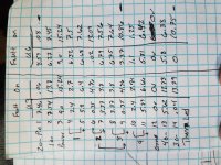
Perry thank you for your knowledge that helps tremendously. Attached is the voltages of u3 and u6. Looks like output 2 and 3 of u3 change. Output 2 is the power led and output 3 is the fault led. The input 2 and 3 are linked to toggle power or fault led. Pin9 high input for 3 goes to soft start pin14 of sg3525. Pin 8 low input for 3 has a pull down resistor that gets fed by pin1 and pin10 of u2 (lm837n). Off of those feeds there are c8 and c15 filter caps to the frequency adjust pot.
Attachments
Do you have a voltmeter on your 12v power supply?
How low is the voltage dropping when the amp tries to start, but doesn't start?
How low is the voltage dropping when the amp tries to start, but doesn't start?
The amp may not power up normally if the voltage is dropping too low.
Powering up with remote applied with B+ may be defeating part of the protection circuit which allows it to power up.
Powering up with remote applied with B+ may be defeating part of the protection circuit which allows it to power up.
So low current was 12.5 rest and 8v through turn on. High current amp turns on but protect light is still on but the remote acts normal. I did notice under high current I am seeing about .06v dc on speaker terminals and a high pitch noise coming from one of the power supply toroids and out of speaker.
I looked at your other post and will compare voltages on u2 and see if I can get the dc voltage down on the outputs.
0.060 isn't significant for this amp. I'd leave it for the last problem to solve.
What type of speaker are you using for testing?
A transformer that makes a high-pitched noise isn't significant, in most instances. Sometimes just moving the windings slightly will stop it.
Does one terminal of the protect LED connect to one of the LM2901s?
What type of speaker are you using for testing?
A transformer that makes a high-pitched noise isn't significant, in most instances. Sometimes just moving the windings slightly will stop it.
Does one terminal of the protect LED connect to one of the LM2901s?
- Home
- General Interest
- Car Audio
- Mmats d3500.1 questions for repair

