Yeah, given the funding to build, [re] locate as required, mine would be made of Ga. marble  : https://blog.polycor.com/hs-fs/hubf...-interior-designer-polycor-georgia-marble.jpg
GM
: https://blog.polycor.com/hs-fs/hubf...-interior-designer-polycor-georgia-marble.jpgGM

Marble is local to Taiwan?
GM
Absolutely. Lots. If you ever have a chance to visit, there is a tourist destination called Taroko Gorge on the eastern side of the island. There are spectacular tight gorges in which the walls are completely swirley marble.
Definite global highlight! Taroko Gorge: Tour Taiwan'''s marble mountains | CNN Travel
Indeed, as astrojet confirmed, marble is one of the most prominent stone around here. In Taroko park, there are walls up to 300m high made of marble. Quite the sight.
In fact, it makes it the cheapest stone over here, so sidewalks are made of marble. They use it in public bathrooms, and the newest Hualien airport has walls and floors made from the same whitish (milky) marble you like.
Local stone factories have piles of "scrap" marble that anyone can pick up for free. Some pieces are up to 1m or more in size. I picked up a marble cutting board and a couple of other pieces as decorations or to put under flower pots, etc...
Here's a couple of pics from only one factory (there must be a 100) with piles of free marble outside, and the Hualien airport.
Ok, back to OP... these stone do indeed make great base or top plate, and look great!
Attachments

That said, built into a [sterilized] sand filled column where its bottom plate is just a divider should add more 'weight'/'fullness'/'tightness' to the speaker's low end response as if clamped down on it somewhat, so ideally needs a very massive top plate and extremely rigid side plates to complete this super low mechanical resonance circuit.
GM
Yes, I am certainly noticing some clarity in the crossover point now they are heavy as an elephant!
Very!! No, though my father came from a long line of farmers dating back to Europe to at least the 14th century AFAIK. I just have a decent size corner lot ringed with various hardwoods that ~ cover the entire property from overhead, which is pretty common for 'old' metro Atlanta in general and my locale in particular, so while we spend very little on AC, we 'pay' in high yard maintenance, especially when high winds and/or lightning damages the trees and of course sometimes the house, etc..
GM
I'm very jealous! Being in London and renting does not afford you much space. I have a small yard and some brick boarders but that's about it! I try and keep woody herbs and lavender but that's all I can sustain year round!
Morning all!
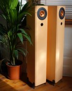
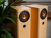
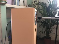
Sorry, I've been quiet, I worked two days flat out to get these done and I am very happy with the results! A few blemishes here and there but all in all they are OK. I just want to say thank you again to all involved that have helped me get this far with them!
I couldn't resist a couple of documentary pics!!!


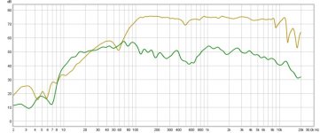
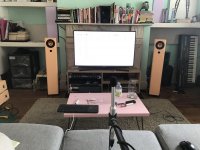
I have started to run some measurements both at near field and listening position. 1/6th smoothing.

Below are both measurements:
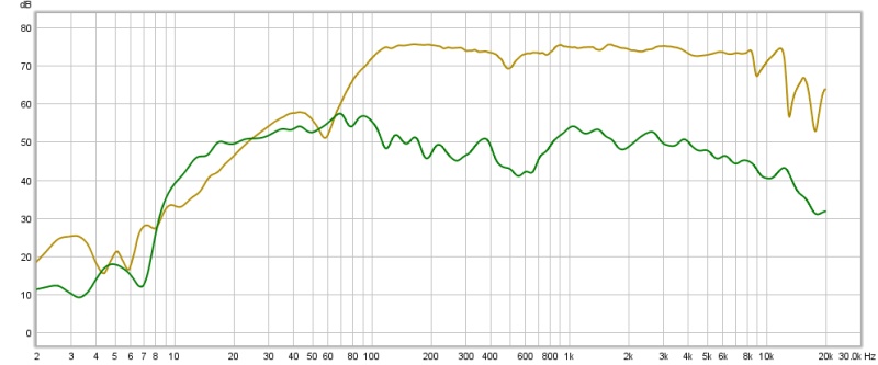
Brown is nearfield at 15mm. I believe this looks as it should! The dip at 60hz is a room mode, I believe.
Green is at listening position. Note the valley between 100hz to 1000hz. Is this my room at play?

My subwoofers are about 50cm behind the floorstanders and I have them inverted on my MiniDSP as this seems to give the best crossover blending sound. I haven't tried any time delay or crossover curves - they are currently set to 90hz with a LR 48db curve on both the mains and the subs. This seems to give the punchiest and nicest sound. Any suggestions on where to go with these settings?
I have to keep reminding myself that these are incredible sounding speakers and a great and flexible set up which I am very thankful of. But... there is always room for improvement and tinkering!
Anyway, thanks again all and look forward to hearing your thoughts!
Cheers, G.
Sorry, I've been quiet, I worked two days flat out to get these done and I am very happy with the results! A few blemishes here and there but all in all they are OK. I just want to say thank you again to all involved that have helped me get this far with them!
I couldn't resist a couple of documentary pics!!!
I have started to run some measurements both at near field and listening position. 1/6th smoothing.
Below are both measurements:
Brown is nearfield at 15mm. I believe this looks as it should! The dip at 60hz is a room mode, I believe.
Green is at listening position. Note the valley between 100hz to 1000hz. Is this my room at play?
My subwoofers are about 50cm behind the floorstanders and I have them inverted on my MiniDSP as this seems to give the best crossover blending sound. I haven't tried any time delay or crossover curves - they are currently set to 90hz with a LR 48db curve on both the mains and the subs. This seems to give the punchiest and nicest sound. Any suggestions on where to go with these settings?
I have to keep reminding myself that these are incredible sounding speakers and a great and flexible set up which I am very thankful of. But... there is always room for improvement and tinkering!
Anyway, thanks again all and look forward to hearing your thoughts!
Cheers, G.
Attachments

Last edited:
2 days to cut, glue and paint 2 enclosures? Time must move slower in your part of the world... I can't do that!
Try a Harsch ... that should be the punchiest XO to try.
That peak rising again at 1kHz would drive me nuts... I'm very sensitive and hate anything that has a peak at 1 kHz.
Have you tried moving the towers around a bit? Sometimes, just a few cm makes a big difference. Side to side, back to front, see if you can resolve most of the dip by moving them a little. When all else fails, I'd use the miniDSP to bring that 1kHz peak down.
Voices must be "nosy" right now.
Oops, just noticed your scale is 10dBs... that's a lot of swinging around...
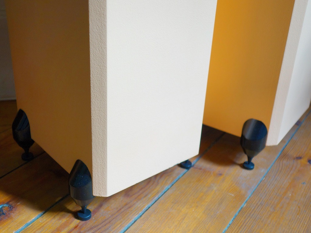
Handsome boxes! What do the insides look like?
I'll try and up some images of the build process soon!
2 days to cut, glue and paint 2 enclosures? Time must move slower in your part of the world... I can't do that!
I cheated a bit by having some of the MDF boards cut by my local joiner! But after the two days I was absolutely exausted!
Try a Harsch ... that should be the punchiest XO to try.
I've googled this but I am still a bit unsure. Is this a preset on a MiniDSP?
That peak rising again at 1kHz would drive me nuts... I'm very sensitive and hate anything that has a peak at 1 kHz.
Have you tried moving the towers around a bit? Sometimes, just a few cm makes a big difference. Side to side, back to front, see if you can resolve most of the dip by moving them a little. When all else fails, I'd use the miniDSP to bring that 1kHz peak down.
Voices must be "nosy" right now.
Oops, just noticed your scale is 10dBs... that's a lot of swinging around...
The upper mid certainly does have some issues and I have tried your suggestion of bring down the 1000hz hump with MiniDSP, it has improved things a lot but there is still more work to do!
I was thinking that maybe BSC might be needed? It's my understanding that these drivers are design with BSC already considered?
I'll do some experiments with positioning soon.
Also, when you say thats a lot of swing, do you mean that the frequency response is very dynamic along the plot? Big troughs big peaks?
Graham,
Nice job with the speakers, and it's hard to believe that you managed all that within 2 days - Congratulations!
Where did you source the feet for the speakers? Is it made out of some kind of plastic/polymer?
Thanks!
I got them from a chap on ebay. I think they are from a pair of factory made speakers as they have no name or any markings of brand etc! They are smart though and Stefan has suggested I get them powder coated as I painted them with Rustoleum and there was some reaction from the metal or previous paint that created light bubbles. I put the ones with blemishes at the back of each speaker. They are quite heavy, and look cast.
Last edited:
@graham, I don't know if you mentioned it before, but have you calibrated your mic for those 90 degree measurements?
No, I have calibrated the sound card but I'm not familiar with the process of mic calibration. Do you care to clue me in, please?
Also, 90 degree measurements? I thought I was bang on axis?
Last edited:
Where does that yellow FR come from?
The green is from previous measurements, but we have no idea where the yellow is from.
A BSC, like 1mH and at least 5 Ohms in your case will bring the whole thing curve from 1kHz down, which would be a bad thing since it already drops starting at 4kHz. You would probably lose most of the high end.
Since you have the miniDSP, why not do a broad notch to bring the 800Hz to 6kHz down?
Here's the Harsch XO thread and how to do it using miniDSP.
S. Harsch XO
1. Set the low pass filter for the woofer as a 4th order Butterworth at central frequency, fc for the XO centerpoint.
2. Set the high pass filter for the tweeter as a 2nd order Bessel at fc.
3. Set the delay of the tweeter equal to 1/2 of the period of one cycle at fc.
4. Use all positive phase on woofer and tweeter.
2. Set the high pass filter for the tweeter as a 2nd order Bessel at fc.
3. Set the delay of the tweeter equal to 1/2 of the period of one cycle at fc.
4. Use all positive phase on woofer and tweeter.
Where does that yellow FR come from?
The green is from previous measurements, but we have no idea where the yellow is from.
= post 147:
Brown is nearfield at 15mm. I believe this looks as it should! The dip at 60hz is a room mode, I believe.
Green is at listening position. Note the valley between 100hz to 1000hz.
I Think he might be referring to the fact that the front of the mic is pointing straight up in one of your shots, which puts it 90 degrees to the speaker. If it is an Omni mic it shouldn’t matter though, as far as I know...?
Zigzag could be cone breakup artifacts?
That's what I thought as well, perhaps I am wrong? It is an omnidirectional mic.
Where does that yellow FR come from?
The green is from previous measurements, but we have no idea where the yellow is from.
The browny yellow is measurement is at 15mm and green is at listening position - both as pictured in post #147.
A BSC, like 1mH and at least 5 Ohms in your case will bring the whole thing curve from 1kHz down, which would be a bad thing since it already drops starting at 4kHz. You would probably lose most of the high end.
Right, got a good idea.
Since you have the miniDSP, why not do a broad notch to bring the 800Hz to 6kHz down?
I have been tinkering with that, I will continue, cheers!
Here's the Harsch XO thread and how to do it using miniDSP.
S. Harsch XO
1. Set the low pass filter for the woofer as a 4th order Butterworth at central frequency, fc for the XO centerpoint.
2. Set the high pass filter for the tweeter as a 2nd order Bessel at fc.
3. Set the delay of the tweeter equal to 1/2 of the period of one cycle at fc.
4. Use all positive phase on woofer and tweeter.
Cheers man, I searched but I must have missed this one, I'll give it a try tonight!
I compared the FR from my (yellowy brown) 15mm measurement to the specifications PDF FR and it looks very similar except over 10k it goes a little wilder. Could this be graph smoothing?
Does anyone know what's going on above 10khz? A weird zig zag pattern, hmmmmm.
A major dip down in the bass range is normally a vertical null, so ~565/60 = ~9.4 ft ceiling height, or.........?
Hmmmmm.
is right! The HF zig-zag is normally cone break-up modes and ~mimic the published response except with a rapid/more erratic roll-off, which shouldn't be the norm unless it's a measurement problem at your end. The real baffler though is the near flat near-field response that should indeed have not only some audible built-in driver BSC, but enough more to maybe a little too much by the cab's audibly identical slope response down to ~60 Hz where the vent is rolling off faster than the driver on a large OB; and if this isn't weird enough, the stepped up response that should just be a minor dip at ~500 Hz, then decaying/'marching in step' at the amplitude up around 400 Hz implies that short of having a large whizzer cone the driver has already shifted into massive [~controlled] breakup, which while possible [re lead guitar, horn drivers]. I'd like to think it's somehow a measurement error, though ATM no clue how this could be............
I remain
GMA major dip down in the bass range is normally a vertical null, so ~565/60 = ~9.4 ft ceiling height, or.........?
Hmmmmm.
The real baffler though is the near flat near-field response that should indeed have not only some audible built-in driver BSC, but enough more to maybe a little too much by the cab's audibly identical slope response down to ~60 Hz where the vent is rolling off faster than the driver on a large OB; and if this isn't weird enough, the stepped up response that should just be a minor dip at ~500 Hz, then decaying/'marching in step' at the amplitude up around 400 Hz implies that short of having a large whizzer cone the driver has already shifted into massive [~controlled] breakup, which while possible [re lead guitar, horn drivers]. I'd like to think it's somehow a measurement error, though ATM no clue how this could be............
I remain
Over dampening, maybe?
- Status
- This old topic is closed. If you want to reopen this topic, contact a moderator using the "Report Post" button.
- Home
- Loudspeakers
- Full Range
- MLTL Floorstanders for Alpair 7MS