I think I'm in the clear but as 2mm in these small port terms is a much higher percentage than a couple of mm off a 50mm (or something lager scale) port I thought I'd be safe and consult. I am getting so excited about putting this together, slowly.
I pick up my 18mm MDF boards from the workshop tomorrow to assemble the 4 walls of the enclosure. I already have 18mm sheets here that I cut the baffle holes and bevels from. I wish I had the space for a table saw but these pre cut boards only cost me £7.
Hopefully Stefan will get the drivers to me maybe wednesday/thursday and the forstner bits to cut holes for the speakon connectors and port holes will be here by midweek too. I found some carpet spray glue under my sink and my stinky sheep wool is ready to go!
Right, when vent mach gets much above 3-5% of the speed of sound in air [depending on the source], it will start loading up, causing audible chuffing, so 'sounds' like you're OK.
If it really loads up though, then it will shift tuning lower, but typically it will be so obviously distorted that folks normally lower the volume and/or change an EQ setting if available. Then again, the mobile audio crowd typically use grossly undersized vents and been known to crank them up higher to increase distortion. Known some HT folks to do it too, especially with a very well known brand, so I guess one man's distortion is another's special effects.
GM
I pick up my 18mm MDF boards from the workshop tomorrow to assemble the 4 walls of the enclosure. I already have 18mm sheets here that I cut the baffle holes and bevels from. I wish I had the space for a table saw but these pre cut boards only cost me £7.
Hopefully Stefan will get the drivers to me maybe wednesday/thursday and the forstner bits to cut holes for the speakon connectors and port holes will be here by midweek too. I found some carpet spray glue under my sink and my stinky sheep wool is ready to go!
Last edited:
😀😀😀 Will do!
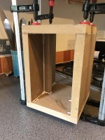
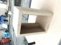
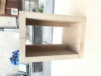
18mm MDF cabinet shells are drying. Baffles will be mounted later then flush trimmed once I have the drivers to make sure my rebates and mounting holes are spot on.
I added some vertical 18mm x 20mm bracing slightly off centre and asymmetrical on opposing sides of the side walls. I hope this will help when employing my idea to bolt the cabinet to the weighted plinth through the bottom of the cabinet by keeping rigidity vertically. I will use an M8 bolt and 30mm washer and spikes inbetween to do this. Please see post no. 38
I wondered if the bracing may disrupt air flow but I (in my limited wisdom) decided it wouldn't. I can always drill holes through them.
Good to see that things are all lined up for your build Graham. Keep the updates coming. 🙂
18mm MDF cabinet shells are drying. Baffles will be mounted later then flush trimmed once I have the drivers to make sure my rebates and mounting holes are spot on.
I added some vertical 18mm x 20mm bracing slightly off centre and asymmetrical on opposing sides of the side walls. I hope this will help when employing my idea to bolt the cabinet to the weighted plinth through the bottom of the cabinet by keeping rigidity vertically. I will use an M8 bolt and 30mm washer and spikes inbetween to do this. Please see post no. 38
I wondered if the bracing may disrupt air flow but I (in my limited wisdom) decided it wouldn't. I can always drill holes through them.
Attachments
Last edited:
It's a lovely evening here in London and I thought I'd do some little bits to get ahead of the game...
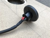
Soldered and heatshrinked my speakons with some leftover van dame 1.5mm cable I have, I managed to get some good mechanical connections and nice flows. The smell of soldering reminds me of something I can't remember but it's a good thing so... great. I also apply 2mm foam around the inside of the speakon socket and tested tight fitting holes for them.
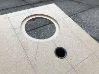
Managed to flush mount my vents. There is about a 1mm gap around the edges due to my router rebate bit not going small enough. I can live with that but I wonder if there is a way to make it perfect?
Also, I'm starting to worry about the braces I put in to the cabs. Will they impede air flow or am I being a hypochondriac. I could (awkwardly) sand them slightly smoother or drill some holes?
The amp to power these is on the way and I managed to get a parasound vamp v3 for £80. I've read generally good reviews and it should provide upwards of 45w which I think is way plenty.
Anyway, have a nice evening, all!
Soldered and heatshrinked my speakons with some leftover van dame 1.5mm cable I have, I managed to get some good mechanical connections and nice flows. The smell of soldering reminds me of something I can't remember but it's a good thing so... great. I also apply 2mm foam around the inside of the speakon socket and tested tight fitting holes for them.
Managed to flush mount my vents. There is about a 1mm gap around the edges due to my router rebate bit not going small enough. I can live with that but I wonder if there is a way to make it perfect?
Also, I'm starting to worry about the braces I put in to the cabs. Will they impede air flow or am I being a hypochondriac. I could (awkwardly) sand them slightly smoother or drill some holes?
The amp to power these is on the way and I managed to get a parasound vamp v3 for £80. I've read generally good reviews and it should provide upwards of 45w which I think is way plenty.
Anyway, have a nice evening, all!
Attachments
Last edited:
Hi Graham,
They are looking great, are you hoping to have the cabinets ready to slip the drivers in when they arrive ?
Re. the gap around the port flare, how are you planning to finish the cabinet ? You could apply some release agent (Vaseline or similar) to the flare & flil the gap with 2part filler, it starts to set in minutes & you could rotate/remove the port before it fully sets, then sand & finish.
Jason
Last edited:
… 1.5mm cable ...
That is way thicker than i would ever use. Be very careful soldering onto the Alpair.
dave
Thanks!
7MS, I am waiting til they arrived before I glue the baffle or rear as I have done all routing from the datasheet and haven't measured the actual driver. Hoping it will slip in like... a very slippy thing?!? 🙂
Excellent idea! I'll investigate that further next month when I have the budget for finishing, thanks!
Hi Graham,
They are looking great, are you hoping to have the cabinets ready to slip the drivers in when they arrive ?
Re. the gap around the port flare, how are you planning to finish the cabinet ? You could apply some release agent (Vaseline or similar) to the flare & flil the gap with 2part filler, it starts to set in minutes & you could rotate/remove the port before it fully sets, then sand & finish.
Jason
I've been trying to think of a makeshift heat sink for he chassis solder tabs. Any ideas?
I'm hoping a couple of seconds of solder time will be safe...
The press-on connectors I have on my Alpair 6.2m are better, in my book.
I'm hoping a couple of seconds of solder time will be safe...
The press-on connectors I have on my Alpair 6.2m are better, in my book.
That is way thicker than i would ever use. Be very careful soldering onto the Alpair.
dave
I expect the A7ms has the same extra connectors that other Alpairs have. We never use them, finding that skinny solid wire soldered to the terminals sounds better.
dave
dave
How would the sound differ?
I expect the A7ms has the same extra connectors that other Alpairs have. We never use them, finding that skinny solid wire soldered to the terminals sounds better.
dave
Chris and i started comparing speaker wires back when Fulton started the whole idea.
In our most recent sessions we started big and kept trying smaller and finding that more information was passed, particularily the small details that flesh out voice & instrument, and that provide the info needed to provide a solid 3D image/soundstage. We ended up settling on a pair of single strands pulled from a CAT5 cable. It is really good. And Frugal-phile(tm). I have seen the same kind of wire (solid/24g-ish) with better doalectric and cryotreated, but have not been able to affors and to try myself.
The speakers we use, like yours, do not need to pass more current than it is capable of and the tiny extra bit of R tends to blunt the overhigh damping in most amps.
dave
Yeah, I wish the old Home Theater Forum [HTF] had archived its DIY section as me and some others posted a lot re proper wire sizing and unfortunately my copies are on a damaged HD, but the long and short of it is that the most efficient over the widest BW is single strand, sized based on voltage drop over distance and where long distances and/or high current are required, then use multi-strand with the strand size governed by the desired HF response.
For many HIFI/HT apps with low power speakers then, the wire size can be a downright tiny single strand, with magnet winding wire's properties historically being the ideal, but no clue how it compares to data, etc., spec cable.
GM
For many HIFI/HT apps with low power speakers then, the wire size can be a downright tiny single strand, with magnet winding wire's properties historically being the ideal, but no clue how it compares to data, etc., spec cable.
GM
Well, I am up for trying this. I am sure I can find some CAT-5 at work. Is a simple LAN cable going to fit the bill?
What confuses me though, is that I will have 2-3 metres of 1.5mm cable running to the speaker cabinet connectors and once it canges to CAt-5 there how would the small section of single core effect things 30cm before the driver?
Surely, by this rule I could put the CAT-5 wire at any point in the cable line and this piece of single core will do its magic there?
My physics isn't fantastic (I was a very enthusiastic secondary school physics pupil!) but I can't wrap my head around it. I'll do some research but if anyone can point me at an explanation I would be keen to understand.
You want the solid core CAT5 — usually used for in-wall runs.
I encourage you to try it in all configs (including CA% + CAT5) and see what works best for you. Use the same colour for both sides.
dave
I encourage you to try it in all configs (including CA% + CAT5) and see what works best for you. Use the same colour for both sides.
dave
Thanks, I am sure there is a drum of it left over after our network was installed at work.
So a whole run of it from amp terminals to speaker connectors running around 2-3 metres would not have any interference or other issues?
So a whole run of it from amp terminals to speaker connectors running around 2-3 metres would not have any interference or other issues?
You want the solid core CAT5 — usually used for in-wall runs.
I encourage you to try it in all configs (including CA% + CAT5) and see what works best for you. Use the same colour for both sides.
dave
It will add around 1ohm series resistance over a 6m loop length, raising effective Qt & thereby significantly altering the box alignment from what was designed. As Dave knows I'm neutral on the subject of single strand Cat5 / 24ga conductors as speaker wire, in the literal sense of the word. I've used 30ga before now. But if you are running a voltage source amp (current source amps are less affected by series R) the altering of the cabinet alignment may be a factor worth considering; if this is felt to be an issue for your limited BW application then I would be inclined to use it for internal wiring only, if you do so at all.
So a whole run of it from amp terminals to speaker connectors running around 2-3 metres would not have any interference or other issues?
Just try it and see.
dave
Well, I am up for trying this. I am sure I can find some CAT-5 at work. Is a simple LAN cable going to fit the bill?
What confuses me though, is that I will have 2-3 metres of 1.5mm cable running to the speaker cabinet connectors and once it canges to CAt-5 there how would the small section of single core effect things 30cm before the driver?
Surely, by this rule I could put the CAT-5 wire at any point in the cable line and this piece of single core will do its magic there?
My physics isn't fantastic (I was a very enthusiastic secondary school physics pupil!) but I can't wrap my head around it. I'll do some research but if anyone can point me at an explanation I would be keen to understand.
No clue, would have to find a piece of LAN and dissect it.
Because it's so short it would be perceived as a much bigger wire WRT current carrying capacity since each termination causes an impedance mismatch. This is why one sometimes sees relatively tiny internal speaker wiring inside a mega watt rated speaker.
Correct depending on how much voltage drop over distance is acceptable, i.e. how much series resistance is tolerable.
Best I can do on short notice: how electricity flows through a cable - Google Search
GM
- Status
- Not open for further replies.
- Home
- Loudspeakers
- Full Range
- MLTL Floorstanders for Alpair 7MS