Hi all, I'll jump straight in and ask for help. After a bit of fiddling around I found that the fuse had blown and following a few of the threads and advice from an ESL builder and parts supplier (WA in Oz) ran a feed from the working panel to the dud and the panel works. I now have been able to remove the access door to inspect the power supply, armed with a circuit diagram from ML US and confirmation that they do not supply component parts (if I find the problem) and to contact a local supplier for a complete board ($$$)
The board itself and components all look in good condition with no obvious signs of overheating, tracking or loose connections. I have checked out the resistors and diodes on the pcb with a multimeter in situ and they seem ok. Which sort of gets me to the extent of my knowledge. From various conversations I read the transformer(s) are often a problem. There is a small one mounted on the pcb without id and a larger one with 486-071091 486-9230 stamped on it. Can anyone suggest my next move, how do I test them? Is more information required?
A forward thanks to anyone that can help, and apologies to the mods if I've posted in the wrong area. I'm in Australia so comment timing may be a bit disjointed.
Checking the resistance of the bias supply's transformer primary winding may show you something if you compare the good and bad speakers. But it also may only show a problem under power, so resistance alone may not be definitive.
In case you missed them, here are a couple threads on Aerius bias supply issues. They don't directly address your problem but provide some background information.
https://www.diyaudio.com/community/threads/martin-logan-aerius-i-ht-board-transformer-kaputt.242731/
https://www.diyaudio.com/community/threads/martin-logan-aerius-no-sound-from-esl-section.290249/
Also, some users log in infrequently, so you may get some help in the future at a random time from someone that can give you more precise guidance.
Much appreciated MS and thanks for the links, After quite a bit of reading up on the EEV forum I have ordered an ESR tester to arrive so I can check the capacitors in-circuit as part of the elimination process. I want to leave removing components from the board till last.
https://www.eevblog.com/forum/index.php
https://www.eevblog.com/forum/index.php
Hmmmm...not sure I've ever heard of a ML supply failing in this fashion.
Can you share a pic of your power supply board? does it look like either of these?


Also, could you share the schematic that ML sent you? I don't think I've seen one for this early style. Perhaps there is something different in this version of the circuit that might be a clue to the cause. I can see that there is a bleeder resistor R100, and the HV is switched on/off in a different manner...perhaps there is something there.
In any case, was the board functioning for you and then started blowing fuses? Or is it a recent acquisition that never worked.
If it never worked, make sure mains selection jumpers are set to 220V.
Let us know what results are from resistance tests of transformer windings. This is such a low current circuit(both the LV and HV sides) the transformer seems the most likely culprit. However, you might also try removing the socketted LM324 to see if it might have failed in a shorted fashion. I guess you might also check LV filter capacitors C9 and C10 for leakage resistance...seems unlikely they could pull enough current to blow the fuse, but worth a look.
Can you share a pic of your power supply board? does it look like either of these?
Also, could you share the schematic that ML sent you? I don't think I've seen one for this early style. Perhaps there is something different in this version of the circuit that might be a clue to the cause. I can see that there is a bleeder resistor R100, and the HV is switched on/off in a different manner...perhaps there is something there.
In any case, was the board functioning for you and then started blowing fuses? Or is it a recent acquisition that never worked.
If it never worked, make sure mains selection jumpers are set to 220V.
Let us know what results are from resistance tests of transformer windings. This is such a low current circuit(both the LV and HV sides) the transformer seems the most likely culprit. However, you might also try removing the socketted LM324 to see if it might have failed in a shorted fashion. I guess you might also check LV filter capacitors C9 and C10 for leakage resistance...seems unlikely they could pull enough current to blow the fuse, but worth a look.
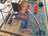
Hi thanks for your interest, I haven't gotten much further since my last comment (life keeps getting in the way) but I have a photo of the board with schematics for the X-over and PS. Looking at the schematic and the board they look to be different animals to me so my next tack is to remove the other board for comparison (speakers are not consecutive numbers) The boards haven't responded to a claw hammer under the binding posts so I will have to remove the bass spkr and punch it out too. I have an ESR meter on it's way I assume another week or so. If the other board and tx's are the same I can compare the R's if it is different I will send photos to ML and see if they have the matching drgs. On the pcb (stand offs removed) with the mntd tx .......bottom L.H corner there is a sliding pot, I assume. Not sure how any of the circuits work at this stage so any help at all is welcome. I will post a photo of the other board if it another model. Time is tight (Booker T and the MGs) atm so progress on my part is slow. Look forward to your opinion as with others too.
.jpg")
Attachments
Aaaah...ok. You have very early version of ML power supply. Brick simple with no auto ON/OFF music sense function. Attached is schematic for the board. The switch in the bottom corner is to adjust the HV supply between 1.9kV and 2.4kV. I have always seen it set to the 2.4kV position.

As you can see, there isn't much to it. The zener diode string is used to clip or regulate the peak output of the transformer with voltage dropped across the 15K resistors. The regulated output is fed to an 8 stage voltage multiplier. If you lift or clip jumper J3 you will completely disconnect all circuitry from the transformer. If the fuse still blows, fault is in the transformer. If this is the case, all is not lost...there are relatively cheap PCB isolation transformers available that can be used (in pairs) to replace. Not pretty, but it works.
I guess it is also possible that a stray washer or nut has found its way underneath the board and shorted out some of the traces.
Last edited:
Hey bolserst, thank you so much this looks more like it. I will try this out at the first chance I get and report back. I may have misled you when I said the stand-offs are removed as I did that myself to check behind. The inside of the cabinet was remarkably tidy with no obvious damage to the board with plenty of damping material. I will report back.
Report: your instincts proved correct, following directions and lifting J3 with a fuse in place the tx started to crackle (like flying an egg) I have removed the tx and will order replacements if you can help further with the spec. I have found a couple of bits of paxolin which I can fashion into a mount and extend the leads back to the board.
The HV switch is set to off. The ESR tester has arrived unexpectedly early but I will play with that later.
The HV switch is set to off. The ESR tester has arrived unexpectedly early but I will play with that later.
Frying eggs...sounds like a replacement transformer is in order. 😉
The usual option is the Triad FP230-25, although some creativity with mounting and wiring will be required.
https://au.mouser.com/ProductDetail/Triad-Magnetics/FP230-25?qs=1hmqIh58KVkAGv9ZoSwEyw==
If you want something that fits the PCB holes with just a little work, the Martin Logan transformer for their later power supply versions can be used. A few years ago they were still available for about $25 in the US. You would have to check on availability in Oz.
To confirm proper operation, you can measure the voltage across C1, the first capacitor in the voltage multiplier with a DVM having 10Meg input impedance. With switch set to the 0 position, you should measure about 300VDC. In the 1 position, about 240VDC.
Attachments
Last edited:
I am in your debt once again. ML US refer me to a local dealer that doesn't supply at component level which doesn't surprise me as there is no volume, ongoing trade and little profit.
What I haven't found is the output tx voltage anywhere, so taking into consideration your earlier reference, would I require 2 of these with the secondaries connected in series for 12v?
Although not original nor as pretty I think I would prefer to run leads from the board to a separate mount for ease of soldering.
You need output voltage somewhere in the 230Vrms to 400Vrms range. The zener regulator will then clip the peaks at 300Vp or 240Vp depending on the switch setting.
The Triad FP23_25 I mentioned has two 115Vrms secondaries which you can put in series to get 230Vrms.
If you plan to mount off the board, perhaps one of these chassis mount/solder lug types would be more to your liking.(although a little pricier)
Bel A41-25-230
https://au.mouser.com/ProductDetail/Bel-Signal-Transformer/A41-25-230?qs=0/2GmT7MRM/CoyLpOZWZqw==
Hammond 185c230
https://au.mouser.com/ProductDetail/Hammond-Manufacturing/185C230?qs=REJuxFWWMVXAtFxZgx1eFA==
Ok, thanks for that, now I've had a look how these panels work it's starting to make a bit of sense to me, I bought them 20 years ago, connected them up and this is the first problem so I haven't thought much about them. I always had them covered for general listening which I take off for a bit of serious listening. I will report back again.
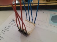
Update, received tx from Mouser, box a bit too big so even though it was wrapped it bounced around inside the box and bent the connection pins, without permanent damage hopefully. Now to fit it, I moved across the 2 resistors to give me a bit of room and made a bracket from a couple of scavenged ones pop-riveted back to back with clearance holes to screw into the panel with self tappers. The top holes are threaded so I could mount the paxolin easily to the brackets. With a couple of vent holes drilled. When I had a closer look at the tx I found I would have put pressure on the connecting wires with that set up so I have to make another pax' plate more like the original pcb with holes drilled for each wire to pass through. Apologies really pressed for time atm so will provide pics of the new plate and the tx asap.
Attachments


Not sure if you have enough room, but you might also consider using the brackets to mount your paxolin sheet vertically and then ziptie the transformer to it.

A word of caution concerning the pinout of the transformer. The primary pins are not in the same order as those of the original transformer.
Refer to the figures in the spec sheet, and be sure to ask if it isn't clear to you.
A word of caution concerning the pinout of the transformer. The primary pins are not in the same order as those of the original transformer.
Refer to the figures in the spec sheet, and be sure to ask if it isn't clear to you.
Thanks bolserst, I will def look at poss vert' mount. I have printed out the spec sheet but will check back with you about the the final connections, Cheers.
Update: I have gone with the top mount as it's a bit squeezy, I finished the pax' board and soldered some tx leads on (again scavenged from a dead coffee machine) which are silicon and braided for heat insulation. (lots of wonderful things inside a espresso machine, hats off to the those that build them)
Oops pressed post accidentally, cont' Connections the tricky bit, looking at the pcb in pic post #5, taking the tx primary are connections closest to the blue bridge connection blocks I have arbitrarily given the original pcb connections L-R as 4-3-2-1 to match the new tx pin-outs and the ones further away as secondary again L-R as 8-7-6-5.
Primary connections: 1 from the fuse 2-3 tx series connections and 4 to ground (not sure of terminology for the last one)
Secondary connections: 5 to J3, 6&7 joined together as tx secondary series connections and 8 to the HV circuit.
I cannot see why at a component level why polarity in the secondary is important for connections 5 & 8 but will take advice from you about that and any other mistakes I have made.
Bolserst, after you set the standard with that drawing above I tried to be as neat as possible, thanks for any further help, shout if you can't understand my meanderings or need more info please.
ps what did you draw that with?
Attachments
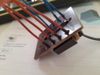
I think I follow your connectivity, and it sounds like you are correctly following the pin numbers rather than pin locations when wiring the transformer to the board.
You also are correctly wiring the secondaries in series. Finally, you are correct that polarity in the secondary (ie 5 vs 8) does not make any difference.
Just to make sure, I marked up one of your pics with PCB connections labeled as you describe using a "B" prefix.
The transformer connections I labeled with a "T" prefix.

You can see that for simplicity I wired each "T" pin to its corresponding "B" pin.
Then to put the secondaries in series:
- remove the jumper in J3 and place it in the J1 jumper location
- add a wire jumper between J2 and J3
Almost forgot, I use Power Point. No reason to use fancy CAD programs for simple drawing and labeling like this
You also are correctly wiring the secondaries in series. Finally, you are correct that polarity in the secondary (ie 5 vs 8) does not make any difference.
Just to make sure, I marked up one of your pics with PCB connections labeled as you describe using a "B" prefix.
The transformer connections I labeled with a "T" prefix.
You can see that for simplicity I wired each "T" pin to its corresponding "B" pin.
Then to put the secondaries in series:
- remove the jumper in J3 and place it in the J1 jumper location
- add a wire jumper between J2 and J3
Almost forgot, I use Power Point. No reason to use fancy CAD programs for simple drawing and labeling like this
- Home
- Loudspeakers
- Planars & Exotics
- ML Aerius power supply blowing fuses