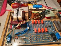
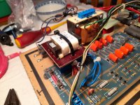
Hi, I've connected up the tx as per instructions including the jumpers but will have to wait till next week to refit the board and give it a run. I will take some photos to post before I close it up.
A question about the HV switch you mentioned in post #6 always being in the higher voltage position, do you have any thoughts why it would not be the case with this speaker, or why there is a switch there at all? I probably won't change it for now as I haven't accessed the second speaker pcb but may in the future if time allows. Thanks again.
A question about the HV switch you mentioned in post #6 always being in the higher voltage position, do you have any thoughts why it would not be the case with this speaker, or why there is a switch there at all? I probably won't change it for now as I haven't accessed the second speaker pcb but may in the future if time allows. Thanks again.
As best I can tell from the images you posted, your voltage selector switch is in position "0" which is the higher voltage position (~2.4kV). Switching to position "1" bypasses two of the zener diodes in the regulator string resulting in ~1.9kV. See schematic including in Post#6.
If you have a DVM with the typical 10Mohm input impedance, you can verify the operation of the switch by measuring the voltage across the first capacitor in the voltage multiplier as details in Post#9. Voltages will be 1/8 of the total output voltage.
As to why the switch was included, my guesses would be:
- so they could use the supply for more than one model
- to provide an adjustment (+/-2dB) to better match sensitivity between panel pairs
Hi, double checked connections then checked hi-lo voltage switch (meter 10 ohm impedance) with supply 236v. Pos 0 = 294 & pos I = 240v.
Assembly and completion will have to wait as in middle of renovations and working space is at a premium. For anyone doing the same the instructions from bolserst are spot on and straight forward. I haven't done any pcb work previous to this and the 40w iron I used proved to be too big and I lifted a bit of the 'track' on the back of the pcb board, I bought a cheap 25w iron to complete the job. I bought a cheap $4 solder sucker from Taiwan that helped with the removal of the old tx. To mark out the tx cable holes on the paxolin board I straightened up the tx pins and with a bit of paper flat on a sponge I gently pushed the connections through the paper and then marked though the holes in the paper directly onto the board for drilling. While out of commission I have removed the floor spikes and replaced them with some small rubber door-stops and will glue some yoga mat (hoping my partner doesn't notice) inside the cabinet walls for extra damping while I have it open.
Next post hopefully will be soon and the full test. Apologies for the drawn out process.
Attachments

Thanks for the pics!
Looking good and your voltage measurements confirm it is operating correctly. 🙂
Awaiting the final chapter of your repair saga.
Looking good and your voltage measurements confirm it is operating correctly. 🙂
Awaiting the final chapter of your repair saga.
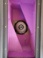
Hi, the ML saga concludes ............ a delay of timber supply gave me a window to wrap it up, which I did today, and as you can see it's looking like a 70s disco, maybe it was the construction glue. The sound is excellent and so the w/d diamonds 10.1 will be returned to the loft. Thanks muchly bolserst (and MattStat at the beginning) I enjoyed the process even if it took an age. thanks for your patience.