Member
Joined 2009
Paid Member
Scott's avatar is Yak_at_third_lake_in_Gokyo
ah, a fantastic spot to visit. I haven't been up to Gokyo lakes. I was in Nepal in 1987 and hiked up around the Annapurna Mountains. I'm pretty sure I ate some Yak meat. Sorry Scott. Nevertheless, a most wonderful place on this earth.
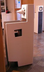
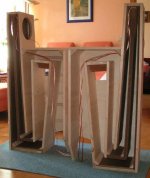
I built this design a couple of years ago. I am thinking about having a second go at it. This time with a driver closer to the specifications of MJK.
Hello,
Can the design of the Martin King's Compact Back Loaded Horn be altered to take a Mark Audio 10p?
Can the design of the Martin King's Compact Back Loaded Horn be altered to take a Mark Audio 10p?
Anyone that have tried to model it in HornResp?
Come June, I will have a go at the design both with a 5" Philips fullrange and a 5" Fostex fullrange.
Come June, I will have a go at the design both with a 5" Philips fullrange and a 5" Fostex fullrange.
As I recall (speaking under correction) Hornresp doesn't currently have the option of adding a Helmholtz resonator at x distance along the horn expansion path, which is the main feature of Martin's design. I've no doubt David could add the facility in time if it doesn't. Off-hand the only widely available software that I know of that currently has this facility is Akabak and AJHorn.
???Hornresp doesn't currently have the option of adding a Helmholtz resonator at x distance along the horn expansion path
Attachments


I stand corrected David (and no offense implied or intended) -that's why I said 'speaking under correction', since I didn't have it installed on the machine I was typing on and I don't pretend to be able to remember everything about it. 😉 Ditto for noting that I was sure you add it if it wasn't.
Hi Scott,
Not a problem 🙂.
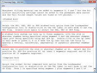
I just thought it worthwhile to let people know that an absorber chamber can indeed be specified in Hornresp, if so required.
The irony is, on doing a quick simulation it seems that the absorber chamber used in Martin's back loaded horn design has virtually no effect on the response, if filling material is added to the system as specified.
Kind regards,
David
Not a problem 🙂.
I just thought it worthwhile to let people know that an absorber chamber can indeed be specified in Hornresp, if so required.
The irony is, on doing a quick simulation it seems that the absorber chamber used in Martin's back loaded horn design has virtually no effect on the response, if filling material is added to the system as specified.
Kind regards,
David
Absolutely; just fired it up here (back on the desktop) & noted the option. 🙂
Very interesting (will take your word for it any time😉 ). It's been a long time since I looked at that box, so many thanks for the extra data!
All the best
Scott
Very interesting (will take your word for it any time😉 ). It's been a long time since I looked at that box, so many thanks for the extra data!
All the best
Scott
How do I add the chamber?
Horn
Section cm2/length cm
S12 45 /27 filling 6 g/dm3
S23 90 /48 filling 6 g/dm3
S34 158 / 53 filling 6g/dm3
S45 248/ 65
S56 452/ 18
DriverChamber 3.8 dm3 depth 14 cm
ResonanceCahmber 3.5 dM3 with a port area of 62 cm2 and 1.2 cm
Horn
Section cm2/length cm
S12 45 /27 filling 6 g/dm3
S23 90 /48 filling 6 g/dm3
S34 158 / 53 filling 6g/dm3
S45 248/ 65
S56 452/ 18
DriverChamber 3.8 dm3 depth 14 cm
ResonanceCahmber 3.5 dM3 with a port area of 62 cm2 and 1.2 cm
David,
So the filling the the chamber flattens out the absorbance dip. How does the response looks if the chamber is empty or perhaps covered with 10mm felt but with the main body of the air volume free of resistive damping fibers.?
So the filling the the chamber flattens out the absorbance dip. How does the response looks if the chamber is empty or perhaps covered with 10mm felt but with the main body of the air volume free of resistive damping fibers.?
I have looked back to my own notes, I only did impedance measrements when I built the first CBLH, with various damping combinations. This time it will be frequency response measurements as well😎
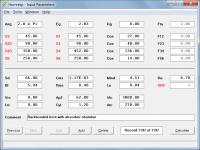
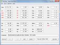
The required input parameter values for the system given above are shown in the attachment. (The Hornresp model has only three segments because the fourth segment is used to specify the absorber chamber).How do I add the chamber?
Horn
Section cm2/length cm
S12 45 /27 filling 6 g/dm3
S23 90 /48 filling 6 g/dm3
S34 158 / 53 filling 6g/dm3
S45 248/ 65
S56 452/ 18
DriverChamber 3.8 dm3 depth 14 cm
ResonanceCahmber 3.5 dM3 with a port area of 62 cm2 and 1.2 cm
Attachments
How does the response looks if the chamber is empty ... but with the main body of the air volume free of resistive damping fibers.?
Attachments
Dear David,
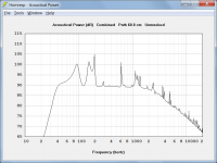
That is a quite scary looking graph!
As I understand it that is with the HR-chamber empty, but is that with fibers in sections 1-3 or are they empty as well?
I will try to make the final measurement in an outdoor corner and measure the summed respons at 2 -3 meters.
That is a quite scary looking graph!
As I understand it that is with the HR-chamber empty, but is that with fibers in sections 1-3 or are they empty as well?
I will try to make the final measurement in an outdoor corner and measure the summed respons at 2 -3 meters.
Hi DrBoar,
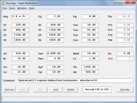
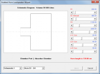
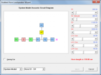
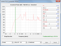
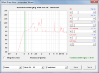
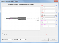
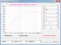
Attachment 1 shows the input parameter values I used to check the model. An OD1 loudspeaker configuration was used, rather than the original SH2 one. Attachment 2 shows the original SH2 (stubbed horn model) response and Attachment 3 shows the OD1 (offset driver horn) response. As you can see, the results are identical.
I interpreted "but with the main body of the air volume free of resistive damping fibers" as meaning that segments 1 to 3 were to be empty as well.
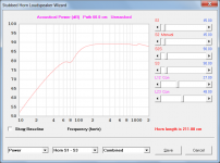
With filling material added to segments 1 to 3 as specified in your earlier post, but with the absorber chamber empty, the response becomes significantly smoother. Attachments 4 and 5 refer.
With filling material already in segments 1 to 3, there is no virtually no change to the response if filling material is then also added to the absorber chamber, as shown in Attachment 6.
Kind regards,
David
I thought the same thing myself when I first saw it, and was a bit surprised that Martin would use it as the basis for a design. I was a little concerned therefore that perhaps the Hornresp stubbed horn model might not be working correctly, so I simulated the same system using a completely different method. Reassuringly, the results were identical so I am confident that the model is okay.That is a quite scary looking graph!
Attachment 1 shows the input parameter values I used to check the model. An OD1 loudspeaker configuration was used, rather than the original SH2 one. Attachment 2 shows the original SH2 (stubbed horn model) response and Attachment 3 shows the OD1 (offset driver horn) response. As you can see, the results are identical.
As I understand it that is with the HR-chamber empty, but is that with fibers in sections 1-3 or are they empty as well?
I interpreted "but with the main body of the air volume free of resistive damping fibers" as meaning that segments 1 to 3 were to be empty as well.
With filling material added to segments 1 to 3 as specified in your earlier post, but with the absorber chamber empty, the response becomes significantly smoother. Attachments 4 and 5 refer.
With filling material already in segments 1 to 3, there is no virtually no change to the response if filling material is then also added to the absorber chamber, as shown in Attachment 6.
Kind regards,
David
Attachments
David, my hero!
Thank you for your tireless work with Hornresp.
I am currently at a chromebook but when I have my PC I will try to look on how much the horn with and without fibers reduce the output of the driver.
As I see it the purpose of a horn/quarterwave pipe is to incresease the radiation resistance of the driver to enable more output/lower distortion. If it does not what is the point of such complicated construction? A bassreflex box offers incresed radiation resistance over a limited range, to be meningful the CBLH and any other complicated design has to be "better" than s simple one. And in this case with 5" fullrange drivers with small surface area and very small x-max, "better" is more radiation resistance with a resonable tradeoff in resonances, peaks and dips.
With regard to the HR chamber, a online calculator suggest the resonance frequency to be 650 Hz.
If I look at MJK graph 7 the horn supress driver output 10-15 dB from 50-200 Hz. Cone displacement is reduced 30-100Hz and the horn output is 5 dB down at 50 and 200 Hz. To tune it down to 250 Hz the slot has to be reduced to 0.5cm or the port hight increased from 1.2 cm to 8 cm or some intermediary combination. I think I will build it with a small round plastic port sealed with some weak glue and then I can cut the ports to different lengths. That 3.5 cm wide slot port is more difficult to change the lenght for.
If I look at MJK graph 7 the horn supress driver output 10-15 dB from 50-200 Hz. Cone displacement is reduced 30-100Hz and the horn output is 5 dB down at 50 and 200 Hz. To tune it down to 250 Hz the slot has to be reduced to 0.5cm or the port hight increased from 1.2 cm to 8 cm or some intermediary combination. I think I will build it with a small round plastic port sealed with some weak glue and then I can cut the ports to different lengths. That 3.5 cm wide slot port is more difficult to change the lenght for.
- Home
- Loudspeakers
- Full Range
- MJK - A Method for Designing a Compact Back Loaded Horn Loudspeaker System