I'm only highlighting what I see from the datasheet. From my comments, you should be able to see that a change in standing current is about 30% which I should have added is for Tj 25C to 175C. That is the extreme, so if your heatsinks are large enough, that should be enough to prevent thermal runaway. It does mean ensuring the heatsinks are able to handle the heating which I suggest should be reckoning on keeping the junction temperature as low as possible. I typically aim to keep heatsink temperatures below 75C (hotter than 50 or 60 (I'd have to check) is now a recognised safety hazard and needs a cage if it is hotter).But please, don't say that the MJ15003 poses a problem, it is precisely this output set that I chose for my amp which has been running almost 24/24 365 for ten years with 23V dc 1.4A bias and I am very far from be the only one to have chosen these output transistors.
Of the JLH's I've built, I must say that I've never used a heatsink with a thermal resistance higher than about 1C/W. Test circuits I have explored have been with old Redpoint 0.55C/W, (both devices on it though) and the worst case I've measured is with 2N3716's which showed an increase in standing current of about 20% over an hour's warm-up time. Though I have not tried MJ15003's, I've seen stable circuits (i.e. not thermally running away) with MJL3281A's and 2SC5200's.
Never had the inclination to test Chinese kits. Would not be surprised if the heatsinks are too small.
If using the original JLH circuit, then some form of current source in the driver only, as shown in huggygood's post, can be applied without using split rails, so the rest of the circuit is more like the original. Q7 could be mounted on the heatsink and would provide some compensation, though I think the actual bias circuitry should be better designed. The possibility for a shorted potentiometer (VR2) is not good practice, but the downside is that the CCS will eat into the voltage margin and may need a higher rail voltage (or the driver rail higher than the main supply) to maintain the output.
Last edited:
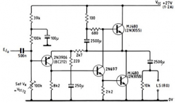
It's the 2003 taken from tcaas .com .@ Huggygood
The shematics you posted looks like the 2003. Is your original single or double voltage, single or double ouput pairs?
Mine are all 69 original schematics with some variant

Sadly, both fake.
+1
I already gave a warning to forum youngsters. Never, ever buy MJ15003/4 from ebay. Sellers with genuine NOS Motorola TO-3 transistors are extremely rare on ebay and especially on Alitard. Don't even trust your local suppliers. And for Pete's sake, Motorola transferred all their semiconductor business to ON Semi 25 years ago !
Last edited:
I certainly can't speak for the 2003 design. I admit that I haven't built it and can't know the balanced supply rail voltages used, nor loads. My reference is the original, single pair of output devices shown. For interest, my friends were a number of high school kids who successfully assembled and modified cheap kits, most of them borrowing speakers from the family sound system. I sourced the MJ15003 transistors many years ago, from a local distributor and had been using them for building and repairing live sound equipment. I can only assume that as they worked fine in PA gear, they were not suspect.
Attachments
Last edited:
Setting up the amplifier when replacing transistors (setting operating currents and voltages).can replace the 2n3055 transistors with mj15003 without any modification on the jlh2003?
It should be possible with most present day, genuine MJ15003 product, to adjust the bias level with the arrangements shown in the original magazine articles. You will need to check that bias with no signal remains stable over 1 hour or more, however.
www.keith-snook.info/wireless-world-magazine/Wireless-World-1969/Simple%20Class%20A%20Amplifier%20-%20.pdf
The problem I found with MJ15003 was considerably higher gain, higher at least than any 2N3055 examples I had in the parts box and it was unstable at 1 amp. collector current and on a heatsink which was comparable to JLH's, as shown in the magazine article. Check the comments on this power transistor gain matter here by John Ellis at #10.
A larger heatsink may have fixed the overheating but I was unaware of what was wrong and it was about 30 years ago, so it had to wait for answers until more recent times.
Last edited:
The decrease in Hfe(I) at higher currents does not contribute to the stabilization of the consumed current (compared to 2N3055).higher gain
Operating point after maximum gain (on the descending part).2N3055
I wouldn't say that the MJ15003 that unstable. The typical Hfe goes from 60@25C to 80@150C at 1A
which one fake??????Most likely the transistors are fake. Open one and show everyone the crystal. Similarly, this
Wik, any transistor where you see a pile of white goo covering or surrounding the die is likely a fake. Real transistors have a die size capable of handling the required output power, and use decent solder mount-down instead of nasty silicone white goo. As an extra caution, the fake devices my be assembled using defective die or die that won't stand up to the voltage rating of a real device.. If you look at the pictures in post #12, the left side picture shows a proper transistor, the right side shows a counterfeit device.
Last edited:
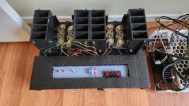
Circuit posted by huggygood is penultimate high power JLH version. Nice sounding amp. Capable up to 45watts classA, depending on power supply voltage. I biased mine at 1.6A and still use forced air by fans on top of heatsinks. Someone on that page discussed the sound and recommended 4A bias! I do not like to run things hot, i like reliability.
I built this one two decades ago, with original outputs from digikey. Occassionaly i fire it, just to enjoy the sound. Yes, its ugly.
I built this one two decades ago, with original outputs from digikey. Occassionaly i fire it, just to enjoy the sound. Yes, its ugly.
Attachments
- Home
- Amplifiers
- Solid State
- MJ15003 transistors that burn out