Perhaps more appropriate is vituixcad . See the first post in this thread https://www.diyaudio.com/community/threads/i-finished-my-speakers-take-a-look.402940/
Oh yeah I really like this second software you suggested. It's much easier for me. I guess now the question is, what would be the best software for creating these frequency response files? I have just been running tone sweeps to see what im looking at. I do have a microphone that will do it. I just need to generate files. I don't have a padded room or anything but it just needs something to go off of. Any ideas there? And thanks again you have been very helpful already!
To do live microphone sweeps, room effect wizard REW is free. It has a gate that stops response before the echoes come back from the room.
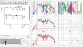
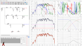
It's been interesting. The horns just cause questionable problems. I have 2 (of many) crossover renditions I modeled. They are slightly incorrect since I don't have an SPL meter. Still notice the first graph that looks terrible in comparison to the second actually sounds better than the second. I guess it goes to show sometimes response isn't the only most important factor. The biggest problem is definitely that 50-ohm potentiometer and horn setup. Do you think that huge impedance spike is okay? I look at that and just assume its going to blow up amps, but it's basically how Peavey had it in the first place other than the Piezo's coming off of it as well. Definitely need it to turn down the horns. I'm not sure what route to go. If this is acceptable impedance I might just leave it like that. If not I might just have to remove them. Thoughts?
Attachments
An impedance of 20 ohm is not going to blow up anything. I'd more worry about the 4 ohm base impedance if I had a one transistor pair output amp, but you have a tube amp. Tube output transformers can develop too high voltage running into 2000 ohms or more. 20 is much less than that.
Honestly yeah I think I have the kink's worked out mostly. Looks like because of that potentiometer, the amp always sees 45-ohm on the horns. Might exceed that or be less in circuit like we were seeing. A couple of other things really helped the sound out a lot. One was a problem with the midrange xover not actually being a complete 1st order. Once I put a 1mH coil on the signal the weird reverberation effect seemed to go away. Really other than the tweeter section is all new since the old piezo's didn't have anything on them, which I will kinda miss but not that sibilance spike they did. The woofer I also adjusted with the larger 2mH coil. It loses a bit in the 500hz area but it makes the bass hit so much more smooth and deep its worth the sacrifice. So now I have some parts to order and and just time to build out the rest. Thanks for all your help!
Personally I would be more annoyed by 10 db loss at 80 hz and 20 db loss at 60 hz, from a 15" driver. I would build a bigger box tuned at 54 hz with a port. I listen to piano & organ media that go down to 60 hz frequently and 30 hz occasionally. The SP2-xt is 3 db down at 54 hz volume is 185 L or 6.53 cuft less the drivers volumes.
I completely agree! Part of my goal was to push a bit more 50-80hz out of it. I still have to turn up the bass in an equalizer but you can actually hear it now and it sounds good.
I'm new here , read some info in speaker impedance have to ask...I have a pair of 3-way 12" woofer cabinets. On the back they are rated like 170 watt and 8 Ohms. Last summer I replaced the 12" in both with a 4 Ohm 12's... . The seller said it would not hurt anything and give me better bass.
So what Ohms is the cabinet (s) now? a tweeter and mid at 8 and the 12" at 4 Yes there is some sort of crossover in there and like a capacitor or two. I don't remember. I know nothing about that technically. The cabinets run as one don't they..? Like it was an 8 Ohm speaker now what is it ?
So what Ohms is the cabinet (s) now? a tweeter and mid at 8 and the 12" at 4 Yes there is some sort of crossover in there and like a capacitor or two. I don't remember. I know nothing about that technically. The cabinets run as one don't they..? Like it was an 8 Ohm speaker now what is it ?
If your source track has a whole lot of bass, like hip hop or modern pop (think Rihanna), then the 4 ohm woofer will consume lots of current and your amp will heat up like a 4 ohm load. If your track has only mid-range like Frank Sinatra or Les Brown and the Band of Renown, then your amp will feel 8 ohms. The tweeter probably has series resistors to lower output to the same level as mid & bass.
I blew output transistors of a single pair MJ15003 amp with a speaker that had two parallel 16 ohm woofers replaced with parallel 8 ohm woofers. The side with the original load, 8 ohms, was fine. The 4 ohm side burned my amp up. I was only using about 10 watts/channel but it was a 4 hour choir rehearsal. Amp had a really crummy heat sink. I have since added fans on the output transistors. The 4 ohms speaker was stolen; bad luck for the next fool that buys it.
I blew output transistors of a single pair MJ15003 amp with a speaker that had two parallel 16 ohm woofers replaced with parallel 8 ohm woofers. The side with the original load, 8 ohms, was fine. The 4 ohm side burned my amp up. I was only using about 10 watts/channel but it was a 4 hour choir rehearsal. Amp had a really crummy heat sink. I have since added fans on the output transistors. The 4 ohms speaker was stolen; bad luck for the next fool that buys it.
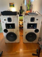
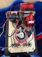
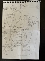
So I thought I would return and give an update for anyone interested. I made some adjustments. In the photos you will see a diagram I drew up if someone is actually wanting to mess around as well. Basically it is updated so the Bi-Amp feature could still work, although if running this way the woofer just bypasses the its filter to let you get all you want out of it. Also note I haven't tested the Bi-amp so be weary. I don't have any more graphs and that was mainly due to my microphone was never really made for the measurements I was taking but I have managed to get it sounding great. The boxes I built are tuned to 50Hz via port, this really helps and the box's are pretty big about 36" by 20" by 13" so by turning up your bass you get some really great low-end that I wasn't even aware these bass-guitar speakers could do. Other adjustments include I went back to the original spec of 2.5mH coil on the woofers and found at least with the old Scorpion woofers that it was just very slightly interfering with the horns. So on the shunt to ground cap I raised it from the originally what they had 50uf to 90uf. Next change was I pegged the horns down to a 3.7uf cap, they are picky and I actually had to go Janzten brand and use 3 different caps to get there each. Next the recommended cap for the JBL tweeters I bought for this project was 2uf and I did end up preferring it and additionally used a 0.57mH shunt coils setup I had laying around which really improved them. The final thing I can't remember if i explained earlier but i put a seperate L-pad on the tweeters since they were rated at 106/db spl rather than the woofer i believe is rated at 98 or 99/db. So yeah you can turn the tweeters down which I'd rather have them matching ratings but not even the original piezo's were rated right, they were too low and unfixable mostly. Not to mention the Horns are something like 125/db spl? and they retain that original 50-ohm potentiometer so you do have a way of controlling everything. It was a fun project. If i were to do it again I may have gone another router tweeter-wise. I did see a piezo tweeter that was correctly rated on a website somewhere so that could be an option. In which case instead of using nice air coil inductors on the woofers like i did i think you may need to use the original choke's that had put on there to deal with noise interference. Anyway that's about it!
Attachments
50/60Hz (or upper harmonics of the mains AC frequency) hum is an amplifier power supply or ground loop problem.I mean it hums without a crossover.
The series coil on a woofer should have no effect on hum.
Don't worry about the high impedance being a problem for an amp (tube or transistor).I just think running 22.5 ohm on an amp not rated for anything like that is wreckless of me. Same with a single 45-ohm horn.
Most "8 ohm" speakers have a low frequency impedance peak well ~45 ohms at their free air resonant frequency (which raises in frequency when put in a sealed box), for instance an 8 ohm Eminence Alpha 12's Fs is ~45 ohms at 49Hz, and 20 ohms at 4kHz:
It's minimum is ~7 ohms, and it's DCR is 6.3 ohms.
When in a bass reflex cabinet, the single impedance peak is split either side of the tuning frequency (Fb), like in this EV12L, 6.4 ohms at 70Hz 31.6 ohms at 35 and 120Hz, dropping to 6.8 ~350Hz, then rising back to over 30ohms above.
Impedance is not one number.
Crossovers made with the assumption speakers are a fixed impedance won't cross at the predicted frequency or slope.
Art

Nice to hear from someone that has the knowledge on this. At some point I stopped being so concerned on the impedance since I've never in my time had an amp have an issue with these speakers (Other than crossover issues). It's just my tube amp that has a hum. It needs some tracing done with a scope, but I moved on to a different amp for now so I can actually listen to music in stereo. Much appreciated on the info thank you!
A lot of things can cause tube amps to hum. Grounding issues, output pairs going out of balance (so the hum doesn’t cancel anymore), bad power supply capacitors, even small microamp level (and perfectly safe) leakage currents from heater to cathode in the input tubes. The latter happens often enough to be a nuisance, and otherwise defies explanation (as in “ this shouldn’t be happening!!!”)
Running a high impedance load isn’t going to cause any of this. Operating with no load can cause instant catastrophic failure, but any load at all no matter how mismatched will prevent that from happening. High impedances will cause high screen current, but any sensibly designed guitar or PA tube amp will have a high enough value screen stopper resistor to prevent failures. And if the screen resistor blows (which I’ve seen happen) the tube just stops conducting and a new resistor puts it back in business.
Running a high impedance load isn’t going to cause any of this. Operating with no load can cause instant catastrophic failure, but any load at all no matter how mismatched will prevent that from happening. High impedances will cause high screen current, but any sensibly designed guitar or PA tube amp will have a high enough value screen stopper resistor to prevent failures. And if the screen resistor blows (which I’ve seen happen) the tube just stops conducting and a new resistor puts it back in business.
- Home
- Live Sound
- PA Systems
- Mixed impedance crossover wiring and amp load