Hello, I have been searching to no avail online to answer a question about impedance wiring, crossovers, and amp load. What I have are some very old 70's PA/Musician speakers that I use both for music on solid state amps and my guitar tube amp as well. These old Peavey speakers had a passive crossover that I am working to redesign and things have become a bit too complicated for me. Originally 2x 15 inch 8 ohm woofers in parallel back to the crossover (so 4ohm), 2x 45-ohm horns in parallel back to the crossover (so 22.5ohm) and 2x piezo tweeters which don't have an ohm rating back to the crossover. It's not a good design, and the tweeters im going a different route with which will match the woofers impedance, and I ended up putting in a single 4-ohm woofer instead of 2-8ohm's. I am also making different cabinets. Each bank of parallel speakers has its own signal coming from the crossover, and the negative terminal just daisy chains around all of the speakers. To me it appears that each bank of speakers effectively parallels all the speakers at the crossover. (All passive crossover design's are this way). Does that not mean they are all paralleled? I read in a few forums that speaker banks at the crossover do not parallel and the amp will see them individually so 4+22.5+4 instead of whatever the 5 speakers would be paralleled together. Is this true? can someone clarify how this makes any sense?
Now for the nitty gritty, 4+22.5+4???? okay so I have also read if you are mismatching impedance that you should use similar impedances. Well, those are definitely not similar impedances. The crossover says (4-ohm) on it but I think this (22.5ohm) may have been damaging my old Randall tube amp. Is this safe to run? What can be done? I don't want to wire resistors in parallel to drop the horn bank more, wasting power and heat, I would rather just completely buy new ones that are rated correctly. They sound decent and I have used them for 25 years on solid state amps with zero problems, but the math makes zero sense to me. So to go a bit further on my impedance question, for simplicity lets say my speakers are all 4 ohm 4+4+4 in each cabinet. Say I connect both cabinet's to left and right channels to my solid state amp. Does that mean my amp is then powering all these banks of 4-ohm speakers? would the two 4-ohm cabinets not also make paralleling and make both cabs 2-ohm total now? Its all very confusing to me. I really don't understand how the crossover which wires 3 parallel speaker banks in parallel doesn't do paralleling. I hope someone can help me I am confused. Thank you all!
Now for the nitty gritty, 4+22.5+4???? okay so I have also read if you are mismatching impedance that you should use similar impedances. Well, those are definitely not similar impedances. The crossover says (4-ohm) on it but I think this (22.5ohm) may have been damaging my old Randall tube amp. Is this safe to run? What can be done? I don't want to wire resistors in parallel to drop the horn bank more, wasting power and heat, I would rather just completely buy new ones that are rated correctly. They sound decent and I have used them for 25 years on solid state amps with zero problems, but the math makes zero sense to me. So to go a bit further on my impedance question, for simplicity lets say my speakers are all 4 ohm 4+4+4 in each cabinet. Say I connect both cabinet's to left and right channels to my solid state amp. Does that mean my amp is then powering all these banks of 4-ohm speakers? would the two 4-ohm cabinets not also make paralleling and make both cabs 2-ohm total now? Its all very confusing to me. I really don't understand how the crossover which wires 3 parallel speaker banks in parallel doesn't do paralleling. I hope someone can help me I am confused. Thank you all!
Passive crossovers block out of band frequencies from drivers that cannot reproduce them, so in a 3 way the three elements are not in parallel. Impedance Z=sqrt(R + (2*pi*f*L)^2 + (1/2*pi*f*C)^2)) So inductors with L series the woofers block highs, and Capacitors with C series the mids & tweeters block lows. Peavey are not cheap so usually there is a capacitor parallel to the woofer to make crossover point 12 db/octave instead of 6, and an inductor parallel the tweeter to make crossover 12 db/octave instead of 6.
Piezo tweeters are a capacitor to the amp so adiditional capacitance may not be necessary. Piezo tweeters are usually blocked by a series resistor to prevent damage. Personally I found the Mallory piezo tweeters on my Peavey 1210's pleasant and the burglar found them so authoritative he carried them off to the pawn shop.
Frankly, I'd leave the crossover alone unless there are electrolytic caps which have dried up. These are cylinders with pinch ring on each end. For PA work you need at least 100 vac rated replacments, and possibly 200 vac if these are 175 watt or higher speakers.
Tube amps are not damaged by too low a load. The high resistance of the tube plate overwhelms any excessive current draw into a short. Tube amps are damaged by open load, as the voltage at the terminal can exceed the 600 v rating of the wire in the output transformer. I put 1000 ohm 3 watt resistors across the output screws of my st-70 tube amp as I occassionally trip over the wiring and disconnect it.
Last edited:
PA speakers get repaired by sleazeballs, so someone replaced the two parallel 16 ohm woofers in one of my 1210's with 8 ohm woofers. This made the parallel impedance 4 ohms, or 3 ohm resistive. My single output transistor pair amp could not handle that current in a 3.5 hour rehearsal and blew the output transistors. You should inspect your speakers to make sure the resistance at the speaker terminals is 6 ohms for 8 ohm rated amp or 3 ohms for 4 ohm rated amp.
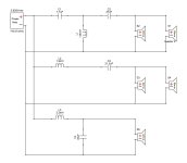
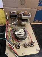
Thanks for that. The problem I still have is weather or not the 22.5 ohm horn is safe for my amps with the other 4-ohm drivers. The KSN1005A Piezo's I loved as a kid but they really do suck. they spike at 5K-6Khz making a horrible sibilance at times. Plus they clearly didn't measure the sound like I am when testing. There is a 3K-4Khz dropout and neither the piezo's or horns are capable of hitting that frequency. Then there's the magnetic power choke they put in at 1000hz, so effectively the horns do 1000-3000 hz, It's awful. I have already rebuilt most of it. Just concerned about the 22.5 ohm mainly. Here is the X-over design currently while i wait on parts. Also a picture of the original crossover before i started hacking it.
Attachments
Piezo tweeters are usually blocked by a series resistor to prevent damage.
That resistor helps to keep the amplifier stable. Some amplifiers may oscillate with a large capacitive load.
Here is the X-over design currently while i wait on parts
If I understand you correctly, you replaced the piezo tweeters with ordinary tweeters (2 of 8 ohm in parallel) and the crossover component values are all meant for 4 ohm, but the midrange section actually sees a 22.5 ohm load. Is that correct?
If so, with this specific crossover circuit, I would expect a much widened passband for the midrange, so the midrange horns get more bass and treble than intended. I wouldn't expect any damage to the amplifier.
So that giant variable resistor (1-Amp, 50-ohm) I thought was just to drive down the DB which the horns need about 9 DB reduction and it sits at about 40ohm in series with them and is how the resistor was originally wired in. So that alone is enough to stabilize the amp from the 22.5 impedance??? <-- My main concern!! Yeah that diagram is something i've been working on and yes its completely mixed order due to many factors (mainly the cost of large inductors is why the mid section is a 1st order). Now that photo of the old crossover shows the original design where they had signal go through the giant variable resistor and then splits one off to the piezo bank with no components and the other goes through two paralleled 5uf caps (so 10uf) and then off to the horn bank. On the woofer it had two 2.6mH magnetic chokes paralleled with each other (so something like 1.4mH in series and then 2x 25uf caps paralleled with each other (so 50uf) shunted to the negative terminal. I mean i completely get what's going on as far as frequency control here. I just want to make sure those horns are safe and not going to break something. The new tweeters whenever i decide what works I will like either get an L-pad attenuator separately for them or just build resistors on to them once i get the freq response graph even.
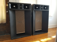
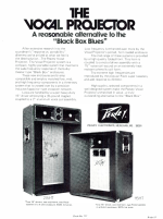
Also these are originally 1974 215ht peavey vocal projectors. After about 25 years I have tracked down the info on those horns and they are actually "paging horns" and these were specifically made for peavey but they still have that high impedance for paging systems (which is super stupid because at the time Electro-voice also made 8-ohm ones which would have been a waaaaaay better option to use) Somewhere i have an electro-voice pdf. These are model PA30-45, 30 watts. I also tried to put an 8-ohm diaphram in one that was blown out once. It works but has a hum, idk maybe something about the driver magnet structure. Either way i finally just replaced it when i found a used one.
Also these are originally 1974 215ht peavey vocal projectors. After about 25 years I have tracked down the info on those horns and they are actually "paging horns" and these were specifically made for peavey but they still have that high impedance for paging systems (which is super stupid because at the time Electro-voice also made 8-ohm ones which would have been a waaaaaay better option to use) Somewhere i have an electro-voice pdf. These are model PA30-45, 30 watts. I also tried to put an 8-ohm diaphram in one that was blown out once. It works but has a hum, idk maybe something about the driver magnet structure. Either way i finally just replaced it when i found a used one.
Yeah that is is unusual to say the least. There was a Peavey 115 vocal master and it only use a single paging horn... which makes sense as they are capable of much higher SPL than the other drivers, so not sure why you decided to use 2 of them in your version.After about 25 years I have tracked down the info on those horns and they are actually "paging horns" and these were specifically made for peavey but they still have that high impedance for paging systems (which is super stupid because at the time Electro-voice also made 8-ohm ones which would have been a waaaaaay better option to use) Somewhere i have an electro-voice pdf. These are model PA30-45, 30 watts. I also tried to put an 8-ohm diaphram in one that was blown out once. It works but has a hum, idk maybe something about the driver magnet structure. Either way i finally just replaced it when i found a used one.
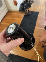
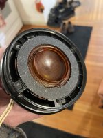
Do you have any pictires of the driver on the paging horn? Is there are transformer inline with them? You say you put a 8ohm diaphram in one of them? That should work fine assuming it fits properly, the hum you describe can't be caused by it so there must be something else going on, what were you powering the speaker with at that time?
The basics of a passive crossover is that it has to be designed for the impedances of the drivers it will be used with... if it isn't then the resulting acoustic response of the speaker system will not be what you had planned. So if the number or impedances of drivers are changed then the crossover needs rework.
The low freq driver/s in a fullrange speaker system with passive crossover essentially determines the overall impedance presented to the amplifier as the majority of power resides in the lower ranges, Good designs typically have a fairly uniform driver impedance across the whole audio spectrum but using different impedance drivers in each range can also work well.
With solid state amplifiers a higher speaker impedance is perfectly safe but less power is delivered, but that works out perfectly with compression drivers which usually have much higher sensitivity and don't need as much power.
Last edited:
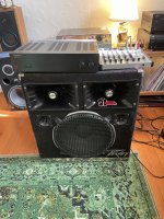
The originals had 2 in them, that's why I even have two in each cabinet. I'll attach an image. Mine are far from original though, the cabinets are long gone. The only difference 2 would really make is a change in impedance correct? I wouldn't think that would affect the SPL of a single horn but idk. No there is no transformer. The woofer's magnetic chokes i thought were transformers at first, I guess they sorta are since they remove AC noise but they are in no way wired with the paging horns only on the woofer. I removed that crap anyway I wanted air-core inductors and it sounds way better with that. Yeah I actually ended up cutting open the one i put the 8-ohm diaphram in since i had replaced it anyway. I mean it hums without a crossover. All of these speakers have individually been tested alone so i could see them on a freq analyzer. The horns are limited from 500hz-3000kz. And all that crap on the front of the horn blocking it blocks upper frequencies and yeah also proabably helps SPL. I cut all that off to get to the driver alone and it still doesn't hit 3khz. Really it doesn't hit that on either the 45ohm or the 8-ohm so roughly around 3khz is my crossover point. To really get everything as good as possible i had to do 400hz and 3200khz on a 3 octave scale as my best bet. The woofer can easily go beyond 400hz so its not an issue, and replacement tweeters will cover down past 3khz to so it should work. I just think running 22.5 ohm on an amp not rated for anything like that is wreckless of me. Same with a single 45-ohm horn. If I could get away with a single one I would do my new design that way definitely. 2 of everything is really stupid but ya know its also a learning process.
Attachments
Yes using 1 horn is entirely possible.. PV did it back in the day and it has become the basis of most modern PA speaker designs. The 22ohm impedance of a single horn is no issue to a solid state amplifier so don't worry about it, just make sure the crossover you build for it is designed around that impedance.

oh look a 115! haha. Its 45ohm for a single, 22.5 for two in parallel. Either way, I should be pretty concerned about my tube amp though correct? That's where it sounds best too. But i Have a 4-ohm output and an 8-ohm output on the tube amp. Would that require me to put in a matching 4-ohm load? I was pretty sure tube amps needed to match exactly. Maybe that's why my tube amp immediately starts over heating.
What if I put in a really high wattage 4 or 5-ohm resistor in parallel with the 22.5 ohm horn bank so it drops the load down to roughly 4ohm? and put a 4-ohm l-pad before all of that to control the volume??? is that a win maybe??
Well, also the 45-ohm is just a guess which isn't good either based off a model that electro-voice made. The resistance on a single horn is about 36.6 on a driver so i mocked that up to being the 45 ohm driver but it could easily be less... i mean if 6.2-ohm resistance speakers can be 8-ohm impedance then i wouldn't see why a 36. something ohm couldn't be the 45-ohm model they advertised... its a 1974 mystery i suppose
Well, also the 45-ohm is just a guess which isn't good either based off a model that electro-voice made. The resistance on a single horn is about 36.6 on a driver so i mocked that up to being the 45 ohm driver but it could easily be less... i mean if 6.2-ohm resistance speakers can be 8-ohm impedance then i wouldn't see why a 36. something ohm couldn't be the 45-ohm model they advertised... its a 1974 mystery i suppose
Last edited:
I just realized that's not a variable resistor. It's a rotary rheostat. And now im trying to understand the difference between it and a potentiometer. One thing is it variably adjusts the signal current. The other thing is that the negative terminal of the horns come back to the 3rd pin and they are 18-ohm until they touch that 3rd pin on ground and that makes them 45-ohm. Absolutely bananas. Somehow that things is designed to retain a 45-ohm load despite the volume (And also despite the parallel wiring which would be 22.5). Maybe someone can understand better. the Rheostat says 50ohm on it so maybe thats it's purpose is to force a 45-50ohm load on the amp regardless of what the drivers are. And who knows what the impedance really is, I am just measuring DC resistance. Maybe these can't run on a tube amp without swapping the horns.
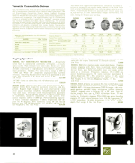
Also here is a couple of useful really old documents attached
Also here is a couple of useful really old documents attached
Attachments
You are treating the crossover as not being there. The amp sees the impedance of the crossover & driver system, not the impedance of any individual driver. You need to put the driver & crossover measurements in a crossover simulator to plot the impedance the amp sees at each frequency. Note this crossover has the typical 4 jack Peavey interface, 2 overall jacks and a high section and low section jack for bi-amping.I just think running 22.5 ohm on an amp not rated for anything like that is wreckless of me. Same with a single 45-ohm horn.
Tube amps can be damaged by open load, ie nothing connected on the speaker terminals. That is the kind of tube amp with vacuum tubes as the output stage and a transformer following to driver a speaker. Many "tube amps" sold these days have a decorative vacuum tube (12AX7) for the input stage and a silicon IC for the output stage. Those are not tube amps. You can protect a real tube amp from damaging the output transformer by putting a 1000 ohm load on the speaker terminals at all times. 45 ohm is a lot less than 1000 ohms.
Compression driven horns are typically much louder at the same driver voltage than woofers. Particularly cheap woofers with small magnets and not much wire in the coil. Most later Peavey products with 8 ohm CD put a 10 to 20 ohm resistor series the compression horn driver to make sure it is not too loud. The premium products also put a tungsten light bulb series the horn driver to prevent damage from loud pops like mike drops or cables pulled out at full volume.
Your 50 ohm rheostat is not shown on the crossover schematic. The difference between a rheostat and a potentiometer is that the rheostat does not have connections at both ends of the winding.
Frankly I believe this is a whole lot of work put into not very good components. You can buy a lot better horns used on ebay than these, particularly. I picked up a pair of Peavey 22A driven horns for $140 one time. These horns are not deserving of air coil inductors. Good 15" woofers are worthy of salvage, but 2" coil woofers are not premium Peavey products. The Mallory piezo tweeters have some fans, me particularly, but they need some crossover work to not be resonant at one frequency. The 1210 speaker put three piezo tweeters facing in 3 directions, which covers the beaming of the flat arrangement of this very early product. The later 1210 had 10" woofers that covered up to 3 or 4000 hz on their own. That will not happen with 15" woofers, the max is about 1800 hz in the 2004 SP2, and that required a wedge shaped cabinet to prevent beaming from the woofer.
Last edited:
Thanks, and I definitely agree with some of that and I appreciate the information/feedback. Basically I'm not trying to spend and I have lots of spare parts. I am weighing replacing the horns with better ones but it is costly in comparison to free. The woofer is not a 2" voice coil anymore.. or I don't know what's under the dust cap anyway lol i blew all those originals out and they kinda sucked. This is a nice 90's 15425 (Scorpion its a 4-ohm 200-watt, also sounds freakin amazing). The air coil conductors are fixing the woofer's low-midrange not the horns and that's why im using them, plus they were just sitting around from other projects. I spent some $$ on some tweeters because its mainly those piezo's are what's awful, at least the horns are warm and have great tone. I imagine the 3-pin rotary rheostat was also to prevent too much current into the piezo's. I noticed that it is acting as some kind of weird L-pad too as the third leg on ground is giving 50Ohm over parallel as well as the 40-ohm (where i have the adjuster set) series part. You're right, it isn't in my diagram but I was never planning on removing it, i just didn't realize what it was doing so i kept it out. I think I'm just going to leave them even though I really wanted to understand what the amp is doing with the current. I guess i really need to study a lot more. I'll probably let the woofer come further up the frequency scale in the midrange than 500, (I mean Peavey had the low x-over at 1000hz) and just use these cheap off brand tweeters to come down lower past 3khz. The piezo's are a pita as you have to put a resistor in parallel just to get the ohm's at all so you can cross them over, then you need a 10-20ohm series resistor to prevent over current from the amp. They weren't having such a big volume issue as much as that awful 3k-4k dead spot and a spike at 5k-6k spike, YUCK, my favorite treble is generally 12k-15k. I hate sibilance. Most people on the forums agree they're not worth it, but i just like history, and its a fun hobby. I've built a few other speakers before but tacking these are a pita that is fun and honestly I haven't spent much so far.
Oh also my tube amp is a Randall RGT 100 HT. It's all tube. so you think higher ohm's would protect it? What would you suggest? It has an 8-ohm a 4-ohm output. If a higher impedance protects it, then why does 4-ohm not hurt it? Also I could wire the horns in series get 90 ohm, then after the rheostat it should be something like 70ohms ish... depends on the DB adjustment needed.
Higher impedance protects transistor amps. These have tiny little 36 gauge wires connecting the pins of the package to the actual die. These have a SOA current limit on each output transistor, which can even be matched for only a 100 ms at a time or if generous, a whole second. Pro grade PA amps have an actual ohm limit, usually painted on the back of the case next to the terminals. Amateur transistor amps are usually okay at 8 ohms, below the rated wattage.
Tube amps with a transformer output cannot be damaged even working into a short. The high resistance of the tube plate (see tube datasheets) swamps any current loss into a load. The different windings of the transformer maximize power transfer into the different speaker impedances. Remember, the impedance of your speaker is a group number, having little to do with the impedance of the various drivers. The impedance will be different at different frequencies.
I suggest your put your drivers & crossovers into a speaker simulator to find out what the actual impedance your amp sees. I am no expert on these, nothing has given correct answers on ubuntu op system. I get better simulations applying kirchoff's laws and running calculations on the equation on a spreadsheet. These are techniques I learned in 2nd year physics course.
Last edited:
For analyzing RLC networks over frequency, LTspice seems to be the preferred simulator. https://www.diyaudio.com/community/threads/installing-the-new-2023-version-of-ltspice.394676/
It includes a lot of semiconductor models that are useless for speaker crossover networks.
I tried a browser version of spice that was supposed to work on ubuntu. It gave wrong answers. Maybe the windows model is more useful.
You will probably get better answers if in addition to the ohms component of your drivers, you use your LCR meter to measure the inductance. It appears you have one, the values of L & C on your crossover schematic are not ones that you buy at a store. Of course be sure to add in the big ohmmite rheostat or L-pad that you left off. Pick a mid position value of the resistances to start out. Include the drivers in your model to find out the impedance as seen at the input terminal of the speaker. You should get a chart of impedance from 20 hz to 20 khz. The minimums and maximums at what frequency are interesting. A 5 ohm impedance on an 8 ohms speaker at one frequency is not scary. Music consists of all frequencies, so the amp only sees the current maximum if producing a sine wave at the frequency of the impedance minimum. Speakers are tested by the factory for watts rating on pink noise, all frequencies.
Last edited:
- Home
- Live Sound
- PA Systems
- Mixed impedance crossover wiring and amp load