I could not disagree more: this might be one of the most overlooked subject, IMHO.
Speaker and amp interaction is a profound subject , indeed. 🙂
High damping factor amp is less problematic, but would not be the best sounding, in my experience so far...
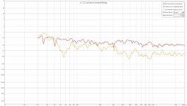
These ones would be easier to compare, first VFET, second IcePower. RED 2nd, Yellow 3rd.
Attachments

Last edited:
Interesting results !
moschfet mentioned AceBass, & i agree it does seem to share some similarities etc. But that's a good thing 😉
Now, if you could auto compensate the temperature Q bump/dip around resonance, then we have a winner 🙂 I know that a number of high power PA amps do actively simulate voice coil temp in real time for protection purposes, so it Can be done 🙂
Maybe we are onto a winner 🙂
Maybe we are onto a winner 🙂
David Birt's method of measuring the dc resistance using a small bias current through the speaker and a 1Hz LPF could be used to compensate the changes. But I would like a faster response so the temperature can track higher peak powers.
So maybe a combination of a self heating series resistor like Yamaha's US5036228 for the short term temperature and Birt's LPF for long term temperature?
If we had a second voice coil we could get faster temperature readings (and motional feedback signal) but I'd like to measure standard single vc speakers.
I would like to back a winner, but all of these (Birt, Yamaha and dual VC speakers) must all be active systems which would seem to exclude them from the commercial Hi-Fi industry. Read Jan Didden here.
So aren't we are talking mainly DIY applications and maybe guitar amps? Is there some way we can make current drive attractive enough to the commercial Hi-Fi industry?
I was hoping mixed voltage drive at LF and current drive at HF could break through since amps can be easily switched between standard and mixed drive? And passive crossovers could be used if they are switched (or replaced) for mixed drive, and mixed voltage drive at LF and current drive at HF does not need an equaliser to remove resonance bumps so you can interchange different speakers and amps. Not to forget the lower distortion is the main driver for change.
"...it can be done 🙂" I think it can.
Hi Zero D,Interesting results ! ...Now, if you could auto compensate the temperature Q bump/dip around resonance, then we have a winner 🙂 ...it Can be done 🙂
Maybe we are onto a winner 🙂
David Birt's method of measuring the dc resistance using a small bias current through the speaker and a 1Hz LPF could be used to compensate the changes. But I would like a faster response so the temperature can track higher peak powers.
So maybe a combination of a self heating series resistor like Yamaha's US5036228 for the short term temperature and Birt's LPF for long term temperature?
If we had a second voice coil we could get faster temperature readings (and motional feedback signal) but I'd like to measure standard single vc speakers.
I would like to back a winner, but all of these (Birt, Yamaha and dual VC speakers) must all be active systems which would seem to exclude them from the commercial Hi-Fi industry. Read Jan Didden here.
So aren't we are talking mainly DIY applications and maybe guitar amps? Is there some way we can make current drive attractive enough to the commercial Hi-Fi industry?
I was hoping mixed voltage drive at LF and current drive at HF could break through since amps can be easily switched between standard and mixed drive? And passive crossovers could be used if they are switched (or replaced) for mixed drive, and mixed voltage drive at LF and current drive at HF does not need an equaliser to remove resonance bumps so you can interchange different speakers and amps. Not to forget the lower distortion is the main driver for change.
"...it can be done 🙂" I think it can.
IanHegglun, have you heard mixed voltage drive at LF and current drive at HF?
From my experience, I suppose what moschfet said is true.
If voltage drives LF, whole amp would sound like voltage drive.
From my experience, I suppose what moschfet said is true.
If voltage drives LF, whole amp would sound like voltage drive.
Theoretically it isn't difficult to make a current drive amplifier that gives you essentially the same small-signal transfer as a voltage drive amplifier for any normal two-terminal passive loudspeaker system, you just need a lot of circuitry for it.
If you want to obtain the same small-signal response as under voltage drive, you could use an equaliser of which the transfer is equal to the admittance (1/impedance) of the loudspeaker. The admittance of any passive loudspeaker system is minimum phase, because if it weren't, the impedance would have poles in the right half plane and be unstable, that is, the loudspeaker would oscillate by itself whenever the input terminals are open or driven with current. Hence, the equaliser has to be minimum phase, so we only have to tune the magnitude of the response.
A conceptually simple approach that would work with any loudspeaker system, is therefore to make some sort of self-tuning, minimum-phase graphic equaliser. You could either design a calibration state machine that measures and adjusts each equaliser band in turn and maybe repeats the whole procedure a couple of times because of interactions between the bands, or let the automatic calibration machine use a wideband test signal and a spectrum analyser, just like is done for manually adjusting graphic equalisers.
The user would, after connecting the loudspeaker to the amplifier, only have to switch it on and press the "calibrate" button. The amplifier would then go through the calibration procedure and store the results in nonvolatile memory.
Theoretically you could even use two spectrum analysers and use the normal music signal as the test signal. One analyser would analyse the spectrum of the music, the other the spectrum of the voltage across the loudspeaker and a bunch of slow control loops would make them equal. I don't think this would work, though, because of the distortion of the loudspeaker. Besides, this variant is not a good idea anyway because it would bring back all compression effects related to voice coil heating.
Actually I wonder whether the arguments for current drive apply at all for frequencies very close to resonance. If they don't, mixed drive with a low driving impedance near the resonant frequency and a high driving impedance everywhere else should work very well indeed (as Ian's simulations already show for the compression effects).
For frequencies far from resonance, the loudspeaker's impedance is dominated by the voice coil resistance and inductance. Both are non-linear: the resistance varies with voice coil temperature and the inductance with voice coil position in the air gap. Besides, the metal surrounding the voice coil has a non-linear B-H curve.
Hence, under voltage drive at frequencies far from resonance, the applied voltage is converted into a current by the voice coil impedance and this current (together with the Bl product) then determines the force excerted on the cone (or dome) of the loudspeaker. Because of the non-linear voice coil impedance, this current has distortion and compression effects that wouldn't have been there under current drive.
For frequencies close to resonance, the impedance is dominated by the back EMF of the loudspeaker. This means that under voltage drive, the back EMF approaches the applied voltage. The back EMF depends on the velocity of the cone (or dome) and the Bl product. As the velocity has a more direct relation to the sound pressure than the force excerted on the cone or dome (less dependent on non-linear mechanical effects), voltage drive could easily result in less distortion than current drive, unless I'm misunderstanding something - which is very well possible, of course; please correct me if I'm not making any sense.
Regarding compression effects, there should hardly be any around the resonance frequency because the back EMF rather than the voice coil resistance determines the impedance. This matches Ian's simulations; the compression under voltage drive basically occurs everywhere except near resonance.
@ IanHegglun
Yes, dc resistance using a small bias current through the speaker and/or a self heating series resistor. The SHR could have a thermal probe etc attached to it, which tracked the changes & auto corrected them.
If it could be done with single vc speakers, so much the better, as it would lower the cost & make things simpler.
Not just DIY applications, or HiFi, but high powered systems as in for concerts & clubs too. Guitar amps benefit from having their own sound & distortions etc, so i wasn't thinking of them, but it could include them as well.
It reminds me of the trick Audio Precision uses in their xformer output stages: include a resistor in the output transformer winding that has the same temperature is the winding.
Use the resistor in a feedback arrangement allows to completely cancel the distortion due to the copper resistance of the winding. Because the resistor tracks the copper temperature, the cancellation tracks over temperature.
I bet this might work well in a speaker voicecoil, although it might be challenging mechanically.
Ian, you could try it with a dual voice coil driver just as a proof-of-concept. That would be an extremely valuable data point.
Jan
Measuring voice coil temperature - proof of concept
I was not thinking of sensing the voice coil temperate in-situ but via a small DC bias current through the voice coil like David Birt used in his AES paper (sorry, I misspelled his name in post #24 - my apology to David Birt).
But measuring the voice coil resistance this way is too slow to catch sudden transients (<1 sec) so I was thinking of adding a self heating resistor in series with the speaker as a thermal model to fill in the first few seconds of temperature reading. This extra resistor reading does not need to be very accurate because the other DC measurement gives good long term accuracy.
With a 0.1 ohm series resistor at room temp the power is around 1/60th of the nominal VC resistance, so this resistor needs to be about 1/60th the speaker power rating, or about 1/4 watt for 20 watt speaker (which typically handles 100W music with a PMR crest factor of 10dB). We also need a thermal mass of 1/60th of the VC. (There are several AES papers dealing with speaker thermal models, I have Zuccattit Jan 1990 but there's a better one here).
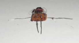
The attached shows a 1/4 watt resistor with 150mm of 0.2mm wire wound on it for 0.1 ohms.
There is a secondary winding of 600mm of 0.07mm wire twisted into the other wire to sense the wire temp with minimal time delay and it's resistance is around 7 ohms so 10mA would give enough voltage change. This fine wire is folded back on itself twice to 150mm for ease of winding and is noninductive to the other winding. Not too hard to wind, but soldering the fine wire to terminals required a magnifier. The resistance increased to 11 ohms when I passed 2.5 amps through the 0.1 ohm wire or about 0.6 watts reaching about 150C. I haven't done a transient test to see if the time constant of the sense resistor is like the voice coil of a woofer yet. But it seems to be in the right ball park.
The temperature information is then used to compensate the power amplifier to remove compression and damping changes. Compensation can be used for either voltage drive amps or mixed current drive (Vdrive at LF). And it can be used to dynamically limit the power to a speaker and turn the PA off if that fails.
Hi Jan,...Because the resistor tracks the copper temperature, the cancellation tracks over temperature. I bet this might work well in a speaker voicecoil, although it might be challenging mechanically.
Ian, you could try it with a dual voice coil driver just as a proof-of-concept. That would be an extremely valuable data point.
Jan
I was not thinking of sensing the voice coil temperate in-situ but via a small DC bias current through the voice coil like David Birt used in his AES paper (sorry, I misspelled his name in post #24 - my apology to David Birt).
But measuring the voice coil resistance this way is too slow to catch sudden transients (<1 sec) so I was thinking of adding a self heating resistor in series with the speaker as a thermal model to fill in the first few seconds of temperature reading. This extra resistor reading does not need to be very accurate because the other DC measurement gives good long term accuracy.
With a 0.1 ohm series resistor at room temp the power is around 1/60th of the nominal VC resistance, so this resistor needs to be about 1/60th the speaker power rating, or about 1/4 watt for 20 watt speaker (which typically handles 100W music with a PMR crest factor of 10dB). We also need a thermal mass of 1/60th of the VC. (There are several AES papers dealing with speaker thermal models, I have Zuccattit Jan 1990 but there's a better one here).
The attached shows a 1/4 watt resistor with 150mm of 0.2mm wire wound on it for 0.1 ohms.
There is a secondary winding of 600mm of 0.07mm wire twisted into the other wire to sense the wire temp with minimal time delay and it's resistance is around 7 ohms so 10mA would give enough voltage change. This fine wire is folded back on itself twice to 150mm for ease of winding and is noninductive to the other winding. Not too hard to wind, but soldering the fine wire to terminals required a magnifier. The resistance increased to 11 ohms when I passed 2.5 amps through the 0.1 ohm wire or about 0.6 watts reaching about 150C. I haven't done a transient test to see if the time constant of the sense resistor is like the voice coil of a woofer yet. But it seems to be in the right ball park.
The temperature information is then used to compensate the power amplifier to remove compression and damping changes. Compensation can be used for either voltage drive amps or mixed current drive (Vdrive at LF). And it can be used to dynamically limit the power to a speaker and turn the PA off if that fails.
Attachments
Last edited:
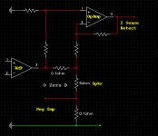
A way to compensate voicecoil temperature changes for mixed current drive (& Vdrive!)
Here's a way to use the 7 ohm winding (see previous post) to compensate a mixed current drive (V drive at LF) for voice coil temp changes.
A generic power amp circuit is attached.
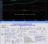
The capture shows SPL plots at 100C and 200C plots overlay the 0C plot --showing the correction works. Notice the speaker voltages are different due to higher VC resistance at 100C and 200C.
This circuit generates a negative resistance equal to the VC resistance increase above 6 ohms at 0C. Resistor R6 is the 7 ohm temperature sensing winding wound together with R5 of 0.1 ohms of wire that connects in series with the speaker. Note R4 is another 0.1 ohm resistor with no temperature coefficient for current feedback.
The Gm of G3 and G4 are 1/7 A/V for unity gain with a 7 ohm sense winding. G2 is 60mA/V from Gm1*Re(0)/R1. Note G3 and G4 can be scaled down if G2 is scaled up.
This circuit uses the 7 ohm sense winding as part of the signal path without extracting the temperature as a control voltage and does not need an analog multiplier which reduces part count and is more reliable. Since G2,3,4 stages are fixed gm they can be implemented using 3 Howland current pumps with standard opamps, or CMOS inverters in linear mode.
BTW you can also use this generic amplifier circuit to compensate for a voltage driven loudspeaker part of an active system. Open the link in my LTspice circuit to disable the current drive and you can see the speaker is temperature compensated in voltage drive mode as well. Nifty
To extract temperature as a voltage a small and equal bias currents can be passed through R6 and R7 then a LPF with gain can be measure the dc voltage between R6 and R7. This voltage proportional to temperature can be used to dynamically limit the amplifier power to the speaker (eg by reducing the clip level of a soft clip circuit) and if necessary turn the PA off if that fails to limit the VC temp below it's maximum safe value.
To recap:
Hi All,...The temperature information is then used to compensate the power amplifier to remove compression and damping changes.
Here's a way to use the 7 ohm winding (see previous post) to compensate a mixed current drive (V drive at LF) for voice coil temp changes.
A generic power amp circuit is attached.
The capture shows SPL plots at 100C and 200C plots overlay the 0C plot --showing the correction works. Notice the speaker voltages are different due to higher VC resistance at 100C and 200C.
This circuit generates a negative resistance equal to the VC resistance increase above 6 ohms at 0C. Resistor R6 is the 7 ohm temperature sensing winding wound together with R5 of 0.1 ohms of wire that connects in series with the speaker. Note R4 is another 0.1 ohm resistor with no temperature coefficient for current feedback.
The Gm of G3 and G4 are 1/7 A/V for unity gain with a 7 ohm sense winding. G2 is 60mA/V from Gm1*Re(0)/R1. Note G3 and G4 can be scaled down if G2 is scaled up.
This circuit uses the 7 ohm sense winding as part of the signal path without extracting the temperature as a control voltage and does not need an analog multiplier which reduces part count and is more reliable. Since G2,3,4 stages are fixed gm they can be implemented using 3 Howland current pumps with standard opamps, or CMOS inverters in linear mode.
BTW you can also use this generic amplifier circuit to compensate for a voltage driven loudspeaker part of an active system. Open the link in my LTspice circuit to disable the current drive and you can see the speaker is temperature compensated in voltage drive mode as well. Nifty
To extract temperature as a voltage a small and equal bias currents can be passed through R6 and R7 then a LPF with gain can be measure the dc voltage between R6 and R7. This voltage proportional to temperature can be used to dynamically limit the amplifier power to the speaker (eg by reducing the clip level of a soft clip circuit) and if necessary turn the PA off if that fails to limit the VC temp below it's maximum safe value.
To recap:
- Mixed current drive (with voltage drive at LF) gives the benefits of distortion reduction from current drive above resonance -- and the voltage drive at LF gives the speaker damping at the low end.
- Mixed current drive allows a speaker to have different inductance values (Le) without needing to change the HF/LF balance setting -- allowing random speakers (something that is not possible with pure current drive) which is needed if we want current drive amps and speakers to be interchangeable like voltage drive amps and speakers are at present.
- With temperature compensation we now get the same damping and roll-off f-3dB over the full temperature range of the speaker -- it can also be used remove compression and crossover misalignment that plagues voltage drive speakers.
- You can easily switch from mixed drive (+Vdrive LF) to pure voltage drive -- so you can drive either standard speakers with this power amp OR (custom) current drive speakers. It's a universal voltage/current drive system that could be attractive to the commercial Hi-Fi industry (and DIYer's!).
Attachments
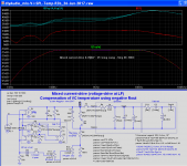
mods to temp comp circuit
Here's the same circuit using ordinary 10mA opamps to replace current pumps for G2,3,4 for the negative R circuit. Easier with standard opamps..... G2,3,4 stages are fixed gm they can be implemented using 3 Howland current pumps with standard opamps...
Attachments
@ IanHegglun
Re "
A way to compensate voicecoil temperature changes for mixed current drive (& Vdrive!)"
Hi, nice going 🙂
So the thermally coupled idea seems to work 😉
Could you not just have R5 for both purposes, & illiminate R4 ?
I use Multisim in place of LTSpice, so i'm unable to make use of Any Zips etc you & others post ! Can you please post the Opamp circuit as an image
@ IanHegglunHi, nice going 🙂
So the thermally coupled idea seems to work 😉
Could you not just have R5 for both purposes, & eliminate R4 ?
... Can you please post the Opamp circuit as an image
Thanks. As mentioned in post #30 I tested the 0.1 ohm wire wound resistor with the 7 ohm secondary wire. That works, it went to 11 ohms with 2.5 amps or 0.6W which is about 38W into a speaker and my 11 ohms converts to 150C. Since the actual vc temp will depend on each speaker, just increase the 0.1 ohm wire length of R4 to increase the indicated temp to suit each speaker. As for the compensation circuit, that works nicely. I haven't built it yet, but sims say it should work.
Having two 0.1 ohm resistors is not absolutely necessary but helpful because the self heating one is copper wire and has the same temp co as the vc which means it models thermal runaway. When you compensate for vc compression with a circuit like I use you can (will?) get thermal runaway in the vc. So I think it is safer to model thermal runaway at this stage until we test if it is safe to not model thermal runaway, and if over-temp sensing must? be used. This means two 0.1 ohm resistors (R4 & R5) because the other one (R4) does not require a temp co, because current drive naturally removes vc resistance compression above resonance.
The LTspice circuit image is now attached. Sorry, I thought everyone had LTspice😱 . The "opamps" are generic voltage gains which can be implemented using the standard 4R "diff-amp" using an opamp. Once I have bench tested one I can post a buildable circuit, but that may take a month or too due to commitments. You are welcome to beat me.🙂
Attachments
@Ian:
I haven't been able to look at this thread for a few days because my Internet connection didn't work. Fascinating thread, and remarkable how much progress you made!
@everyone:
I've done some simulations to see if you can gain much by using a bandpass/notch filter combination rather than lowpass/highpass for combining the voltage and transadmittance feedback signals. It actually didn't help much, because the Q of the bandpass/notch filter has to be really low to prevent bumps in the transfer. On top of that you then have to tune the filters depending on the resonance frequency of the loudspeaker, which makes it less generic. So all in all, I think Ian's lowpass/highpass filters are better.
@ IanHegglun
Thanx for the pic 🙂 I see what you mean about compensating for vc Temp etc with the wire 😉 No, not everyone uses LTspice. I tried it but prefer Multisim.
@ MarcelvdG
Sorry to hear about your www downtime ! All Feedback is welcome. Pun intended 😀
Thanx for the pic 🙂 I see what you mean about compensating for vc Temp etc with the wire 😉 No, not everyone uses LTspice. I tried it but prefer Multisim.
@ MarcelvdG
Sorry to hear about your www downtime ! All Feedback is welcome. Pun intended 😀
Hi MarcelvdG,The attached pdf contains the details of my simulations. I stole the simulation schematic from Ian and modified it.
No worries. I'm pleased someone can use my sim circuits to try out different things.
@ All
BTW I put copyright in most of my sim circuits and documents to avert blatant plagiarism (publishing it under a different name without acknowledging the source when it's known). So anyone is free to pass any of my stuff on to others as long as the copyright is not removed, but most people already know all this.
Anyway, what I really need to say is that MarcelvdG PM'ed me about his speaker crossover article in Linear Audio Volume 2, 'Simple Loudspeaker Correction Filters' https://linearaudio.net/article-detail/2101. I had forgotten about this article and this covers just what I needed to know for my next step in designing a speaker and amp system using mixed current drive with voltage drive at LF. Thanks MarcelvdG.
I realise discussion on multi-way speakers and crossovers is normally done in their respective talk areas (not this solid-state area), but because we are working on designing and building a non-standard complete system starting with a non-standard current drive power amp I hope that it's OK for now. There may be other threads active in the multi-way speaker and crossover areas so if someone frequents those then it would be nice if they mention this thread in case they aren't aware of it.
Back to Marcel's Linear Audio article on his simple equaliser. I now realise that pole shift filters, like MarcelvdG's, are in common use in active systems to extend the LF roll-off of a tweeter or woofer (or mid-range) so the crossover filter slopes dominate approaching the crossover frequency and then you don't need to use ridiculously high-order crossover slopes to get a flat enough final SPL plot. And you can choose a crossover frequency closer to the speaker's resonance and maybe get away with a two-way system rather than a 3-way.
Well, that's how I interpret it; correct me if I'm way off. MarcelvdG is the experienced and knowledgeable one in this area; I'm just starting as a beginner on multi-way speaker and crossover design.
Is there a good document available on the Internet covering this topic like Marcel's article but free?
I think you can find quite a number of hits when you search for Linkwitz transform circuit. That works on the same principle: cover the poles with zeroes and put new poles where you want them.
- Home
- Amplifiers
- Solid State
- mix current drive with voltage drive at LF?