A few years ago I blew one channel on my Cyrus III (SR 32151) and had it repaired by Mission. The problem now is that 1 channel of the amp doesn’t really work until you turn the volume up to about 11 o’clock when both channels snap back to near equal levels – using an attenuated audio lead to avoid the need for ear muffs .
I believe there may be a fault in the HPA7 volume control section and note it contains a ST 89340 chip. I’ve been unable to get any information on this chip from the ST website and wondered anyone might be able to suggest an option, given that I now live in New Zealand.
I believe there may be a fault in the HPA7 volume control section and note it contains a ST 89340 chip. I’ve been unable to get any information on this chip from the ST website and wondered anyone might be able to suggest an option, given that I now live in New Zealand.
In this case this thread could be of interest:
http://www.diyaudio.com/forums/soli...hematics-later-models-wanted.html#post1998327
http://www.diyaudio.com/forums/soli...hematics-later-models-wanted.html#post1998327
Hi sonokeling,
ICs do not fail to be intermittent. What you have there sounds more like an intermittent connection.
So, where do you think you may find intermittent connections in there? The speaker output jacks are a natural, and it's easy to create a broken connection by having a speaker connector get banged sideways. Also, since it's been repaired before, try re-seating the ribbon cables between the input selector / volume PCB and main PCB. Be careful with these, you don't want to ruin the connection. It's also possible that you may have a cable or input jack problem. Further testing on your part can eliminate those problems.
Now for the really important part you should be prepared for. If you manage to remove the main PCB, you have created a problem (assuming the previous repair was done right). These use a special "plastic" transistor insulator and the heat sink is rough. You must do one of two things now. Either purchase the exact same insulators (they are not cheap) and completely clean the mounting area. If you are going to use any other type of transistor insulator, you must reduce the surface roughness of the mounting area to close to mirror smooth. This means starting with a course file and working down to a fine file to almost finish. This ensures a true surface and you must take your time. You will be tired after one side. Finally, a careful finish sand with 600 grit wet/dry paper using a true block. This is also how I actually do this, so I'm not recommending anything that I don't actually do myself. Once the mounting area is both really smooth and clean, you may mount the outputs as you normally would using thermal compound (not the stuff for computers!).
If you are not prepared to do this, do not open it up.
-Chris
I doubt it.I believe there may be a fault in the HPA7 volume control section and note it contains a ST 89340 chip.
ICs do not fail to be intermittent. What you have there sounds more like an intermittent connection.
So, where do you think you may find intermittent connections in there? The speaker output jacks are a natural, and it's easy to create a broken connection by having a speaker connector get banged sideways. Also, since it's been repaired before, try re-seating the ribbon cables between the input selector / volume PCB and main PCB. Be careful with these, you don't want to ruin the connection. It's also possible that you may have a cable or input jack problem. Further testing on your part can eliminate those problems.
Now for the really important part you should be prepared for. If you manage to remove the main PCB, you have created a problem (assuming the previous repair was done right). These use a special "plastic" transistor insulator and the heat sink is rough. You must do one of two things now. Either purchase the exact same insulators (they are not cheap) and completely clean the mounting area. If you are going to use any other type of transistor insulator, you must reduce the surface roughness of the mounting area to close to mirror smooth. This means starting with a course file and working down to a fine file to almost finish. This ensures a true surface and you must take your time. You will be tired after one side. Finally, a careful finish sand with 600 grit wet/dry paper using a true block. This is also how I actually do this, so I'm not recommending anything that I don't actually do myself. Once the mounting area is both really smooth and clean, you may mount the outputs as you normally would using thermal compound (not the stuff for computers!).
If you are not prepared to do this, do not open it up.
-Chris
Thanks for taking the time to explain some more about these amps Chris,
I've had the thing apart before to replace all the diodes with Schottky's. This was before the problem I mention occurred, and I must have got lucky because it worked just fine.
The exact cause of the problem probably goes back to the damage I needed the thing servicing for, when the volume was accidentally turned up by the remote to almost full when it got stuck down a cushion and not realising this adjusted the volume down on the unit and caused some sort of power surge.
Having gone for ultimate fidelity I'd bypassed all the fuses and switches in the back and well, the rest is history.
Many thanks again for your help. As you suggest I will carefully check all the cables and connectors; otherwise, if it was possible to follow the audio tracks, I was thinking to swap out the remote volume for a standard volume control like Mission used in the Cyrus SL, or whatever it was called.
Hi sonokeling,
Understand that different components were created for specific jobs. This doesn't make them better, just suited to a specific purpose. The normal rectifiers are about the best for the job they perform. A sharp cutoff characteristic is going to generate more noise than the original parts.

In fact, this has possibly caused your insurance to become null and void. Your equipment no longer meets and safety codes and there is no performance gain to show for it. I'm very concerned of course, from a warranty person's viewpoint and also simply because these changes are not well thought out. Where ever you heard of this change, mentally mark them as a source of faulty information. I hate to say it, but people recommending this are completely irresponsible. They are the people I have been cleaning up after for years and years.
Please, for many reasons, return your amplifier to stock configuration immediately! I'm going to insist on this.
-Chris
Soft recovery types? If not, you were better off with the original parts. The other thing to watch for is the reverse voltage rating, Schottky diodes tend to be rated for lower voltages.I've had the thing apart before to replace all the diodes with Schottky's.
Understand that different components were created for specific jobs. This doesn't make them better, just suited to a specific purpose. The normal rectifiers are about the best for the job they perform. A sharp cutoff characteristic is going to generate more noise than the original parts.
I wouldn't call this "ultimate fidelity"! 😱Having gone for ultimate fidelity I'd bypassed all the fuses and switches in the back and well, the rest is history.
In fact, this has possibly caused your insurance to become null and void. Your equipment no longer meets and safety codes and there is no performance gain to show for it. I'm very concerned of course, from a warranty person's viewpoint and also simply because these changes are not well thought out. Where ever you heard of this change, mentally mark them as a source of faulty information. I hate to say it, but people recommending this are completely irresponsible. They are the people I have been cleaning up after for years and years.
Please, for many reasons, return your amplifier to stock configuration immediately! I'm going to insist on this.
-Chris
Hi Chris,
I can only agree that it was a lesson hard learned! The amplifier was returned to its near original configuration before being sent off to Mission and has remained that way since. I purchased the schottky diodes from Russ Andrews, rated for the positions they were fitted. However, I agree completely with your comments on diodes and only use well-rated bridge rectifiers in all my new builds. I guess I meant to put that ultimate fidelity comment in quotes.
I see the restoration of the Cyrus 3 as an interesting project, which has become a lot more likely following your guidance and the links to schematics posted by tiefbassuebertr.
So, I carefully checked all ribbon cable connections and the obvious stuff like the speaker output jacks Chris mentions. Replugging the unit, there was no difference. From switch on the Cyrus III starts in mute mode, rotating the volume takes it out of mute with a small click through the speakers. On my unit this happens on the right channel immediately, but the left channel stays at a much lower volume until a specific point at 11 o'clock on the volume dial, when it too has a slight click and the volume balance returns. Obviously at this volume setting an unattentuated input would be extremely loud. I attentuate the signal through a pair of cermet pots in-line with the interconnect, which actually allows me to enjoy the amp at a fair level of fidelity - it pretty much matches the quality of my Adcom unit. I'm pretty certain the problem is in the pre-amp section, which is chip based. Does anyone have experience of a similar issue or any suggestions how I might diagnose this preamplifier issue. Thanks for all the help provided so far.
The whole voltage gain (if volume control stands at full power) must be arround 500So, I carefully checked all ribbon cable connections and the obvious stuff like the speaker output jacks Chris mentions. Replugging the unit, there was no difference. From switch on the Cyrus III starts in mute mode, rotating the volume takes it out of mute with a small click through the speakers. On my unit this happens on the right channel immediately, but the left channel stays at a much lower volume until a specific point at 11 o'clock on the volume dial, when it too has a slight click and the volume balance returns. Obviously at this volume setting an unattentuated input would be extremely loud. I attentuate the signal through a pair of cermet pots in-line with the interconnect, which actually allows me to enjoy the amp at a fair level of fidelity - it pretty much matches the quality of my Adcom unit. I'm pretty certain the problem is in the pre-amp section, which is chip based. Does anyone have experience of a similar issue or any suggestions how I might diagnose this preamplifier issue. Thanks for all the help provided so far.
In general I hate cascading of a line amp with voltage gain factor arround 10-times and a power amp stage with voltage gain factor between 30 and 60 (for todays program sources with output voltages between 1Vss and 5Vss). Long before you will reach full power position, clipping point is present (and damaged tweeters in much cases).
Until this day I haven't understand this often to observe practice.
Therefore I go on and remove the active line amp in much cases and put the output wire from volume control direct to the input of power amp. In case of the Cyrus III you will not find a mechanical potentiometer (attenuator) like an Alps. Instead of this there is a electronic attenuator and a custom programable operating controller (MCU).
If you have a schematic of this part, you can try to remove the active line stage (an operational amp e. g.) and instead of this you must now introduce a bypass between the output of the attenuator and the power amp input. But please note, you will find mainly surface mounted devices and therefore you need a lot of experience, even with presently schematic.
Your mentioned solution with the pre-attenuation at the input is also helpful. However then you have still an (discrete or integrated) op-Amp with high gain factor (and additional THD source) in serial to the signal.
Last edited:
I like the solution you offer, which fits with my own minimalist approach. I was a bit shocked by all the smd on inspecting the inside of the Cyrus III, and have not yet been able to locate a schematic which would allow me to do exactly what you describe. There was a cheaper version of the Cyrus III which may have had a normal pot for the volume - Cyrus SL..? If I could get a look at the insides of one of them and this showed how to replace the flashy IC-pot for a Sfernice or some such, it might be all that's needed.
However, I get the feeling the best long term solution would be a return to base or the local cyrus agent, but thanks for your advice.
However, I get the feeling the best long term solution would be a return to base or the local cyrus agent, but thanks for your advice.
If you have a possibilty to get the main PCB without components of your Cyrus III from your local service department you will get much more easy to create a schematic about reverse engeneering (threre is no multilayer PCB, only two-layer).
Hi sonokeling,
There are times when that volume control IC can be damaged. If you replace it, the amp should be returned to it's normal operation.
To remove these ICs from double sided PCBs, get out your dremel tool. Install a cut-off disc (abrasive) and get it spinning. Carefully cut the legs of the IC off right at the body of the IC. After this is done, your should be able to carefully remove each pin without damaging the PCB. Adding a touch of fresh solder to each pin should make the job much easier. I like to use a "solder sucker" placed on the component side, then heat up the pin you're over and suck the solder out once the solder has melted. This should leave you with no lead in the (now cleaned out) hole. You can also pull the leg out by using pliers and your iron on the opposite side. The danger here is pulling before the solder is completely melted and ripping up a trace. There is no rush with this work.
Hi tiefbassuebertr,
To be honest with you, I don't think that Cyrus even has any blank PCBs to start with. They would be completely useless to them for one, and this would be a break from the industry norm. You should know that. Almost every manufacturer I can think of will not make bare PCBs available. The cost of building one up would be astronomical compared to the value of a mass produced board that is populated already.
You haven't thought this through, have you? Firstly, you are making assumptions about various products with very little information to go on. Secondly, you have failed to understand why there is a gain stage there to begin with. Those gain circuits do other things than provide gain.
Please, look up the various ICs used in the audio chain and read the applications sections of the data sheet. It's very important that you do this before making any suggestions or performing any more ill advised modifications to other equipment. I sure hope you haven't done this for customers!
There is a truth that you really need to get your head wrapped around here. A manufacturer will generally not put in anything into a product that isn't necessary for some reason. Therefore, never remove stuff unless you are going to provide an improved replacement for it.
I have to say that you make far too many assumptions, and I am uncomfortable about that.
-Chris
There are times when that volume control IC can be damaged. If you replace it, the amp should be returned to it's normal operation.
To remove these ICs from double sided PCBs, get out your dremel tool. Install a cut-off disc (abrasive) and get it spinning. Carefully cut the legs of the IC off right at the body of the IC. After this is done, your should be able to carefully remove each pin without damaging the PCB. Adding a touch of fresh solder to each pin should make the job much easier. I like to use a "solder sucker" placed on the component side, then heat up the pin you're over and suck the solder out once the solder has melted. This should leave you with no lead in the (now cleaned out) hole. You can also pull the leg out by using pliers and your iron on the opposite side. The danger here is pulling before the solder is completely melted and ripping up a trace. There is no rush with this work.
Well, can you imagine how busy the PCB would be if those were all through hole parts? 😱I was a bit shocked by all the smd on inspecting the inside of the Cyrus III
Well, exactly. I've mentioned this more than once, and also the reasons behind that decision.and have not yet been able to locate a schematic which would allow me to do exactly what you describe.
Yes, in this case that is your best option. In the end, you will have a very reliable unit.However, I get the feeling the best long term solution would be a return to base or the local cyrus agent, but thanks for your advice.
Hi tiefbassuebertr,
You're kidding me - right? Come on now, that is your quest. You do it.If you have a possibilty to get the main PCB without components of your Cyrus III from your local service department you will get much more easy to create a schematic about reverse engeneering (threre is no multilayer PCB, only two-layer).
To be honest with you, I don't think that Cyrus even has any blank PCBs to start with. They would be completely useless to them for one, and this would be a break from the industry norm. You should know that. Almost every manufacturer I can think of will not make bare PCBs available. The cost of building one up would be astronomical compared to the value of a mass produced board that is populated already.
This is really terrible advice!Therefore I go on and remove the active line amp in much cases and put the output wire from volume control direct to the input of power amp.
You haven't thought this through, have you? Firstly, you are making assumptions about various products with very little information to go on. Secondly, you have failed to understand why there is a gain stage there to begin with. Those gain circuits do other things than provide gain.
Please, look up the various ICs used in the audio chain and read the applications sections of the data sheet. It's very important that you do this before making any suggestions or performing any more ill advised modifications to other equipment. I sure hope you haven't done this for customers!
There is a truth that you really need to get your head wrapped around here. A manufacturer will generally not put in anything into a product that isn't necessary for some reason. Therefore, never remove stuff unless you are going to provide an improved replacement for it.
I have to say that you make far too many assumptions, and I am uncomfortable about that.
-Chris
If you have a possibilty to get the main PCB without components of your Cyrus III from your local service department you will get much more easy to create a schematic about reverse engeneering (threre is no multilayer PCB, only two-layer).
Hi tiefbassuebertr,
You're kidding me - right? Come on now, that is your quest. You do it.
To be honest with you, I don't think that Cyrus even has any blank PCBs to start with. They would be completely useless to them for one, and this would be a break from the industry norm. You should know that. Almost every manufacturer I can think of will not make bare PCBs available. The cost of building one up would be astronomical compared to the value of a mass produced board that is populated already.
Therefore I go on and remove the active line amp in much cases and put the output wire from volume control direct to the input of power amp.
This is really terrible advice!
You haven't thought this through, have you? Firstly, you are making assumptions about various products with very little information to go on. Secondly, you have failed to understand why there is a gain stage there to begin with. Those gain circuits do other things than provide gain.
Please, look up the various ICs used in the audio chain and read the applications sections of the data sheet. It's very important that you do this before making any suggestions or performing any more ill advised modifications to other equipment. I sure hope you haven't done this for customers!
There is a truth that you really need to get your head wrapped around here. A manufacturer will generally not put in anything into a product that isn't necessary for some reason. Therefore, never remove stuff unless you are going to provide an improved replacement for it.
I have to say that you make far too many assumptions, and I am uncomfortable about that.
-Chris
Hi Chris,
my proposal to get PCB without components is no kidding spell. From Thule Audio I have order this (from the most amp models) because I have make the service therefore (only for the German distributor). This PCBs are a great help to find out residual misprints and checking out various modifications. Also for reverse engeneering such PCB's are helpful
If there are full support for service work from the manufacturer (wasn't the case by Thule Audio) and also appropriate Service Manuals (in the kind of that one from Kenwood or Sony) available (not only schematics), such additional PCB's nonsense of course.
BTW - if I set bypass and remove aktive parts for the line preamp stage, you can be sure that this was carefully thought out and prepared. When I perform in consumer equipment such modifications without an audible improvement in sonic results after this, what otherwise sense would have such work?
I haven't do this and other modifications until this day by the Cyrus III and related models, because I haven't get a service manual from Cyrus III and it's successors.
But from the view to the number of solded devices, it is worth considering to perform a reverse engineering by the next repair order and to develop ways to improve. This I have make by the components from Thule Audio (mainly SMD like Cyrus III and successors), but I am sure, by the Cyrus III devices this is much more easier, because there are much less design shortcomings concerning the avoiding of hot spots (through thermal overloading) and thus much less modifications against this and dried caps.
What do you estimate how many Cyrus devices (III until 8-XP) in Canada are in circulation respective in use?
Last edited:
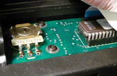
I was very interested by Chris's comment about Dremelling the chip out of the board, so took another look inside the Cyrus III at the HA7A Control Board.
http://j.imagehost.org/0436/cyrus_Ha7a_control_board.jpg
A websearch for ST 89340 returned nothing, but Z86E21F1 produces the goods, and tells me that this is a logic controller. Removing the transformer to gain access to the four T10 bolts on this board will probably be all that's needed but there's nothing that looks like a DIP package on the other side, based on the solder points visible from the inside of the unit.
I'll wait for further instructions before proceeding.
Thanks!
the orig. AN's are from Zilog and on the device from your pic is from ST MicroelectronicsI was very interested by Chris's comment about Dremelling the chip out of the board, so took another look inside the Cyrus III at the HA7A Control Board.
http://j.imagehost.org/0436/cyrus_Ha7a_control_board.jpg
A websearch for ST 89340 returned nothing, but Z86E21F1 produces the goods, and tells me that this is a logic controller. Removing the transformer to gain access to the four T10 bolts on this board will probably be all that's needed but there's nothing that looks like a DIP package on the other side, based on the solder points visible from the inside of the unit.
I'll wait for further instructions before proceeding.
Thanks!
http://www.zilog.com/docs/z8/appnotes/an0220.pdf
http://www.zilog.com/docs/appnotes/an0049.pdf
from
Zilog - Home
and datasheet also from Zilog
Z86E21 pdf, Z86E21 description, Z86E21 datasheets, Z86E21 view ::: ALLDATASHEET :::
in the attachement the photo of your URL, because such URLs sometimes short-lived
Attachments
Last edited:
Hi sonokeling,
The volume control IC is on the main PCB, the selector IC is closest to the rear jacks. You can't miss it.
Hi tiefbassuebertr,
There is no problem having a Cyrus component properly serviced. The only problem I can see is that you want to service these products but do not have approval to do so. As far as improving the performance of these products is concerned, you would have to do a great deal of study before being able to make that call. Please don't forget that the buffers that are installed are there because the absolutely need to be there. This design is only as complicated as it needs to be. If you do remove these buffers, the unit absolutely will sound different. However, this change in sonics will be at the expense of signal quality. Just because someone says a change sounds better does not make it so! Anyway, you will have increased distortion for sure.
One might ask why I am so sure about this. If you take the time to look at the data sheets for the volume control IC and the input switching IC, you will have your answers. To remove the buffers means that you really should have simply built your own amp in the first place. Forgo remote electronic volume control (and it's excellent channel to channel balance) and electronic input selection (so now the unit is bigger and makes a mechanical click noise).
I have a Cyrus system, and it's excellent by most standards. Could it be improved - sure! But that means doing a careful parts survey and knowing exactly what you are doing. I'm thinking about doing this very thing to my Mono X amplifiers and Pre X preamplifier. It's going to be a while before I'm ready to do this because I need to gather the correct improved parts first. Ones that actually fit properly. One thing that I can't do is improve anything by removing parts that you have deemed unnecessary. All those bits need to be there.
Also, don't touch the uP! You can't hope to make any good changes there! It always comes on with volume down, a safe way to start. The uP code can be changed if required by all service centers, and by the factory. Those sharp engineers at Cyrus will provide updated files when and if they become necessary. I said engineers because that is what Cyrus hires for product development, real live people who are well versed in analog circuit design and digital circuit design and programming. You should take a minute to respect the level of skill of the people you feel are not up to the level you feel they should be. I can also tell you that these are very nice people as well. I've met them and can vouch for the professional way the execute their duties. They also have better test equipment at their disposal than I do, and far better than most technicians will see in one place. The equipment must also pass a critical series of listening tests before a design is released to production.
There are other brands out there that I'll agree could use some improved design work, but Cyrus is not one of those. Those are the units you have had success with, but you can't apply the same ideas and procedures to a Cyrus product. To start changing things in a Cyrus is to most probably reduce it's performance.
I know where you are coming from, but I feel you are mistaken with these Cyrus models. To learn much more about some circuitry, look up the ICs you see in the audio path. You should be able to rationalize some of what you see then.
-Chris
It has been a while, but finally got around to changing the pesky little op amp (I think I got the right one!). I'm unlikely ever to venture in again as this was a little beyond me and my poor little Goot soldering iron. Managed to dislodge the old one, and damage the track into the bargain. Replacement was an identical unit, and miraculously was able to be fitted on second attempt (I destroyed the first one).
Powered-up, all diagnostic lights OK....exactly the same fault, though the amp does sound better now - well, it would if it wasn't hiding in its box in a cupboard in my shed.
Powered-up, all diagnostic lights OK....exactly the same fault, though the amp does sound better now - well, it would if it wasn't hiding in its box in a cupboard in my shed.
- Status
- Not open for further replies.
- Home
- Amplifiers
- Solid State
- Mission Cyrus III