Hi.
I have a pair of 751 and a pair of 751 Freedoms. I have recapped my Cyrus One with great success and now wonder if I should upgrade the components on the 751 crossovers, rewire them inside, and mess about with the filling. Does anybody have a circuit diagram for the crossover(s) and any experience of modifying them.
Many Thanks.
The 752 maybe similar. It has series inductor to bass with 15uF bipolar in series with 10R across the driver.
Tweeter has 6.8uF polyester, series 1R and a shunt choke across the driver - a typical 2nd Order
Tweeter has 6.8uF polyester, series 1R and a shunt choke across the driver - a typical 2nd Order
That seems to make sense from what I've seen of the Mission 751. It's a SEAS polycone with a natural rolloff around 3kHz if it's like the Vintage SEAS P21 RE.The 752 maybe similar. It has series inductor to bass with 15uF bipolar in series with 10R across the driver.
Tweeter has 6.8uF polyester, series 1R and a shunt choke across the driver - a typical 2nd Order
SEAS VINTAGE DRIVERS
An externally hosted image should be here but it was not working when we last tested it.
Uploaded with ImageShack.us
A zobel on the bass ought to work well to improve the rolloff. There's not much room to work here, but replacing the (50V) non-polar electrolytics with fresh ones ought to help. You might squeeze a 250V 6.8uF tweeter polypropylene on that crossover board. 🙂
A bit of rubbery carpet underlay stuck to the top and bottom panels would do no harm. Be wary of putting any on the sidepanels unless they are braced or it could make things worse.
Last edited:
Thanks for the input. I've swapped the speakers out for some 750s and I'll pull the crossovers out over the weekend and have a look. Is it Ok if I post some pictures then ?. I'm not too sure about where the 6.8uF tweeter polypropylene should go. I was tempted to replace the caps with Ansars - Cricklewood Electronics - CCTV. CCTV Equipment. CCTV Systems. Digital CCTV Cameras. Does that sound good ?. I'm a bit new to this so any pointers (idiots guides) very welcome. I've also got some Chord Epic to rewire the innards.
I’m sorry - ref the 6.8uF I should have including the following photos from inside the crossovers. I’ll know a bit more when I get them out altogether. This is all a bit new to me.
[URL="http://i879.photobucket.com/albums/ab352/freddypipsqueek/IMG_0074.jpg%5b/IMG"]http://i879.photobucket.com/albums/ab352/freddypipsqueek/IMG_0074.jpg[/IMG[/URL]]
[IMG][URL="http://i879.photobucket.com/albums/ab352/freddypipsqueek/IMG_0076.jpg%5b/IMG"]http://i879.photobucket.com/albums/ab352/freddypipsqueek/IMG_0076.jpg[/IMG[/URL]]
[IMG][URL="http://i879.photobucket.com/albums/ab352/freddypipsqueek/IMG_0078.jpg%5b/IMG"]http://i879.photobucket.com/albums/ab352/freddypipsqueek/IMG_0078.jpg[/IMG[/URL]]
Before you start buying expensive non polarised capacitors, try testing your speakers with Holmimpulse, with a PC and cheapo pc microphone.
My 752 tweeters are showing similar loss of lower frequencies and too strong higher frequencies, that my TDLs had due to drying ferrofluid.
I also found one cabinet was buzzing during the sweep with a distortion bump at 200 Hz, this was due to the bass driver bolts having gone a bit loose and easily fixed
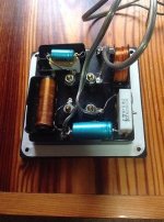
All I see for sure there is a 3.3uF bypass capacitor and a 5.6 ohm wirewound. You'll need to trace out the circuit. Maybe unglue some components too. Usually hot glue which melts easily if messily in hottish water.
Most capacitors are safe up to 85C, which gives you some margin. Of course you then have to dry out the crossover with warm air. The blue cylinders are non-polar electrolytics, which deteriorate with age, being full of wet electrolyte.
Those Ansar polypropylenes look OK, but size will be a consideration. Putting them on bass shunts can raise issues of resistance change over Non-Polars too. Easy on tweeters.
Does anybody share my notion that biwireable speakers are popular because they give the maker more room on the back of the speaker plug plate to fit crossovers? 😀
Last edited:
I've replaced the caps and tweeter resisters and added some supertweeters with very good results. Has anybody upgarde the bass units in the 751/53 and if so with what units. the bass is a a litte light. Thanks.
I've replaced the caps and tweeter resisters and added some supertweeters with very good results. Has anybody upgarde the bass units in the 751/53 and if so with what units. the bass is a a litte light. Thanks.
Revisiting an old thread here.
Freddy, are your speakers the 751? I can't see the capacitor values on the crossover. Can you please share?
Bump.. (on behalf of Dewdrop and myself)
Had a look at mine and it appears to have a 1uF cap in parallel with the resistor which I don't understand - unless I'm reading it wrongly. I would be great if somebody with a bit more electronic knowledge could explain.
Thanks
Had a look at mine and it appears to have a 1uF cap in parallel with the resistor which I don't understand - unless I'm reading it wrongly. I would be great if somebody with a bit more electronic knowledge could explain.
Thanks
One would want to see a clear shot of the XO board with values of the caps and resistors stated.
Photobucket
Thats a link from the previous poster (Freddypipsqueek on page 1). I can tell you on the other side of the cap it says 1MFD which I assume means 1uF? ..I couldn't see any other ref to capacitance on it.
Thats a link from the previous poster (Freddypipsqueek on page 1). I can tell you on the other side of the cap it says 1MFD which I assume means 1uF? ..I couldn't see any other ref to capacitance on it.
The white component labelled 3.3K/100V isn't a resistor, it's a 3.3 uF film capacitor. Together with the 1 uF electrolytic wired in parallel, the total tweeter capacitor (?) seems to be 4.3 uF.

Many thanks to Dissi and Lojzek - that helps a lot and makes sense to me now, and will help anyone coming across this post in the future.
Thanks guys!Many thanks to Dissi and Lojzek - that helps a lot and makes sense to me now, and will help anyone coming across this post in the future.
Sent from my SM-G935F using Tapatalk
The interesting point is why did they use a film and electrolytic combination?The white component labelled 3.3K/100V isn't a resistor, it's a 3.3 uF film capacitor. Together with the 1 uF electrolytic wired in parallel, the total tweeter capacitor (?) seems to be 4.3 uF.
Sent from my SM-G935F using Tapatalk
- Home
- Loudspeakers
- Multi-Way
- Mission 751 Crossover Circuit Diagram