Has anyone a link to a good quality all fet/mosfet minimalist class A/B amp? Something around 60watt into 8ohm.
Also, has anyone had any experience with the original Trans Nova amps designed by Jim Strickland some years back? Not the later Hafler amps. I was wondering if anyone has actually heard one of these amps in comparison with more conventional designs.
Also, has anyone had any experience with the original Trans Nova amps designed by Jim Strickland some years back? Not the later Hafler amps. I was wondering if anyone has actually heard one of these amps in comparison with more conventional designs.
I described one in detail here on diyaudio you may have already seen. http://www.diyaudio.com/forums/showthread.php?s=&threadid=6338
It is minimalist in that it has only 2 fets in the signal chain per channel (50W class A). I'm reluctant to mention it though because everybody around here is probably sick of me going on about it by now. It sounds ok though.
It is minimalist in that it has only 2 fets in the signal chain per channel (50W class A). I'm reluctant to mention it though because everybody around here is probably sick of me going on about it by now. It sounds ok though.
First off, study this follower circuit:
http://www.audiodesignguide.com/my/Cool_Follower1.GIF
The outputs in the original design were three pair of the small plastic TIP41/42 type, replace these with one pair of Semelab BUZ900/905. The one pair will be more than enough for 60W/8R or 100W/4R. The input pair may be any small signal type suitable for 10mA or so, the MPSA06/56 would be fine. Use ±15V for the supply for the input pair and 1200 ohms for the bias resistors (instead of the 390 ohm), use a pair of 100 ohm trim pots (instead of the 0.18 ohm). The BUZ need no emitter/source resistors. The capacitor need only be a 1µF (or larger) film type across the gates of the outputs.
Hook the output of this follower straight to ground, since the sources of the BUZ are the case this is easy, just use no insulator and ground the heatsinks!
To convert to a TransNova output stage all we need is a 5K input resistor to the bases of the input pair and a 100K feedback resistor from the same point to the center tap of the power transformer. We will need a regulated ±15V supply for the input pairs, one supply to drive as many channels as needed. We will need a ±40V supply (30-0-30V 150VA or larger), one per channel is needed.
Set the 100 ohm pots to about 25 ohms, then turn on and adjust for the idling current desired in the output stage. After the temperature and bias stabilize (just turn up the bias until the heatsink is as warm as you want it to be, the actual value is unimportant) then trim these again for DC off-set.
This circuit will only work for lateral MOS like the BUZ or the J50/K135 type. IRF type will blow up.
The amount of power in class A is only limited by the size of the heatsinks, and moves into class AB for loud peaks only.
If BUZ 900D/905D are used with minimum bias (100mA) and suitable heatsinking and supply voltages are used, 250W in class AB is possible out of only one pair of outputs.
djk,
How I wish you could post a schematic of this circuit you are talking about as well as for many of your other insightful posts.
How I wish you could post a schematic of this circuit you are talking about as well as for many of your other insightful posts.
Some links - Designed by: Andrea Ciuffoli
Designed by: Andrea Ciuffoli
On this page you have the 😎"Cool Follower 99"😎
And several other of Andrea Ciuffoli interesting Amp Ideas.
Both tubes & solid state
😉 This is probably one of WWW most interesting Sites For Amplifiers
Thanks, 🙂 djk
for giving us the hint - and remind us
------------------------------------------------------------------
- Also remember that a Class A PUSH-PULL is TWICE as effective
as a Class A with Current Source.
- Or half the heat - for same output WATTS. = half as big Heatsink
- Or +3dB, double output power - for same heat.
- for whatever those 3 extra dB is worth 😱
Can be just as well to find a Speaker with extra 3dB Effiency.
Or why not both!
/halo
Samuel Jayaraj said:djk,
How I wish you could post a schematic of this circuit you are talking about as well as for many of your other insightful posts.
Designed by: Andrea Ciuffoli
On this page you have the 😎"Cool Follower 99"😎
And several other of Andrea Ciuffoli interesting Amp Ideas.
Both tubes & solid state
😉 This is probably one of WWW most interesting Sites For Amplifiers
Thanks, 🙂 djk
for giving us the hint - and remind us
------------------------------------------------------------------
- Also remember that a Class A PUSH-PULL is TWICE as effective
as a Class A with Current Source.
- Or half the heat - for same output WATTS. = half as big Heatsink
- Or +3dB, double output power - for same heat.
- for whatever those 3 extra dB is worth 😱
Can be just as well to find a Speaker with extra 3dB Effiency.
Or why not both!
/halo
Samuel Jayaraj :
How I wish you could post a schematic of this circuit you are talking about as well as for many of your other insightful posts.
I can really use a new computer. I bought a scanner with the idea of posting hand drawn schematics, but I need a newer computer to run it. But my 16 year old car is also demanding attention.
halojoy:
Andrea Ciuffoli
I really enjoy Andrea's site. Converting the follower to lateral MOSFETs allows for a higher input impedance and makes the design stable over temperature. Making it a TransNova output stage with voltage gain without adding any extra semiconductors is kind of trick!
Folks,
while browsing the web I came acros this qute FET amp. I've build it and it works fine when you can control oscillations.
I now use it for my small studio monitors while mixing recordings.
You HAVE to build this as described on Aren's page.
Aren's FET amp
Let me know what you think...
while browsing the web I came acros this qute FET amp. I've build it and it works fine when you can control oscillations.
I now use it for my small studio monitors while mixing recordings.
You HAVE to build this as described on Aren's page.
Aren's FET amp
Let me know what you think...
minimalist a/b amp
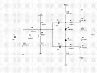
Here is my minimalist class a/b amp. Does a bit over 50W. Distortion @ 1w is 0.25% second order. The bias ciruit and power supplies are not shown. Insert your favorite temperature compensated bais circuit. Needs +/- 40V and +95V (not much current @95v) . Input impedance is rather low, could add a input buffer like the one used on the Zen4, but then it would not be minimalist. I have the output bias set @ 20mA. Could go higher and run more class A but then I would need bigger heat sinks and I really can't hear the difference anyways.
Here is my minimalist class a/b amp. Does a bit over 50W. Distortion @ 1w is 0.25% second order. The bias ciruit and power supplies are not shown. Insert your favorite temperature compensated bais circuit. Needs +/- 40V and +95V (not much current @95v) . Input impedance is rather low, could add a input buffer like the one used on the Zen4, but then it would not be minimalist. I have the output bias set @ 20mA. Could go higher and run more class A but then I would need bigger heat sinks and I really can't hear the difference anyways.
Attachments
SumTingsBurning,
sorry for being sceptical, but have you measured those data on a working equipment implemetning the shematic you have enclosed to your letter?
It does not utilize any global feedback, neither a Sziklai output configuration wich means that the last stage would do a lot of distortion. (It is neither class A...) If things were so easy...
Please correct me if I am wrong, but if this amplifier is high fidelity then I have to start everything from scratch.
>It does not utilize any global feedback, neither a Sziklai output configuration wich means that the last stage would do a lot of distortion. (It is neither class A...) If things were so easy...
Sorry, what's a Sziklai output configuration?
I gotta look that one up.
I measured the distortion on 2 different pieces of test equipment and got the same result. No it does not use global feedback.
I was trying to see how good an amp I could make without global feedback using a minimal number of parts. There is nothing unusual here, a voltage amp followed by Mosfet followers.
1 watt 0.25% FET distortionSumTingsBurning said:>It does not utilize any global feedback, neither a Sziklai output configuration wich means that the last stage would do a lot of distortion. (It is neither class A...) If things were so easy...
Sorry, what's a Sziklai output configuration?
I gotta look that one up.
I measured the distortion on 2 different pieces of test equipment and got the same result. No it does not use global feedback.
I was trying to see how good an amp I could make without global feedback using a minimal number of parts. There is nothing unusual here, a voltage amp followed by Mosfet followers.
could sound as some Tube Amps, or even better?.
And is that BAD or GOOD!?? compared with Real Hifi...
/halo
1 watt 0.25% FET distortion
could sound as some Tube Amps, or even better?.
And is that BAD or GOOD!?? compared with Real Hifi...
Yes it does sound like a tube amp. It's not the best amp in the world, only better than some.
Now if you say tube amps are not real HiFi...
I think some people in the tube amp forum might disagree with you.🙂
I know some disagree,SumTingsBurning said:Yes it does sound like a tube amp. It's not the best amp in the world, only better than some.
Now if you say tube amps are not real HiFi...
I think some people in the tube amp forum might disagree with you.🙂
but I define hifi as low distortion.
That does not mean that hifi always gives
the best sound-experience with your ears & mind.
There are many that does not mind a certain distortion.
And certain types of distortions better than none.
for my own I prefer to know that my soundwaves are
as close to the recording as possible with todays components,
and with my wallet's capacity.
/halo - do not mind doing some teasing of tube-guys!
he still admire most of them - they know things he doesn't know 😎
SumTingsBurning,
Sometimes I just look but don't see. At 1 W the measured distorsion is OK. I had 10 in my mind. Anyway, I would really like to hear this amp. Years ago I designed too such circuits, but then I learned too much about amplifiers and realised that such a circuit will distort just too much at higher levels. (Actually 5 W is high here...) So I never built such simple power amp. But I am always curious...Never heard any like this.
You can find a lot of information about the Sziklai output stage, just make a search for "complex emitter follower". This is a thread I started about this configuration and there is a lot of valuable information.
bt
P.S. to everyone: Please do not try to make a solid state amplifier wich has a distorsion of a tube amp. Really good amps sound just the same regardless of what kind of active elements are used. The pure reproduction of the material stored on the media has to be the aim, nothing more and nothing less.
Banfi T. amp - Your version of this?
could you please post a schematic, Banfi T..
I already got one "Banfi Amp".
I think that was a preamp.
These types of minimalistic amps is very good for
HeadPhones. With impedance 32 ohms and higher.
###############################################################
Thanks for all schematics here!
What I find to be 😉 THE BEST MINMALISTIC AMPLIFIER 😉
I will publish in my collection of AMP Schematics.
(Does only apply to schematics posted in this very thread)
I want to thank all the visitors at my collection.
Thank you!.
Statistics: 3712 connections /11 days!
350/day. - A lot of downloads of schematics and PDF.
I opened the server 6th of february.
So a lot of amplifier interested people will see your Schematic
if I put it in my Server. I can help almost anyone.
Would need some more Tube amps. More of the simple-but-good-kind.
###############################################################
/halo - 😉 😎 The Great Webmaster 😎 😉
If you decide to design or even build this type of minimalist amp,Banfi T. said:SumTingsBurning,
Sometimes I just look but don't see. At 1 W the measured distorsion is OK. I had 10 in my mind. Anyway, I would really like to hear this amp. Years ago I designed too such circuits, but then I learned too much about amplifiers and realised that such a circuit will distort just too much at higher levels. (Actually 5 W is high here...) So I never built such simple power amp. But I am always curious...Never heard any like this.
could you please post a schematic, Banfi T..
I already got one "Banfi Amp".
I think that was a preamp.
These types of minimalistic amps is very good for
HeadPhones. With impedance 32 ohms and higher.
###############################################################
Thanks for all schematics here!
What I find to be 😉 THE BEST MINMALISTIC AMPLIFIER 😉
I will publish in my collection of AMP Schematics.
(Does only apply to schematics posted in this very thread)
I want to thank all the visitors at my collection.
Thank you!.
Statistics: 3712 connections /11 days!
350/day. - A lot of downloads of schematics and PDF.
I opened the server 6th of february.
So a lot of amplifier interested people will see your Schematic
if I put it in my Server. I can help almost anyone.
Would need some more Tube amps. More of the simple-but-good-kind.
###############################################################
/halo - 😉 😎 The Great Webmaster 😎 😉
Hi halojoy,
I am very busy nowadays, but I will post some of my older designs later this week, after I finished my much more ordinary power amp with MAT04s. By the way, the shematic you have is a power amp wich is working according to the simulations. (I have a working simulator now thanks to the forum 🙂 )
bt
I am very busy nowadays, but I will post some of my older designs later this week, after I finished my much more ordinary power amp with MAT04s. By the way, the shematic you have is a power amp wich is working according to the simulations. (I have a working simulator now thanks to the forum 🙂 )
bt
Okay, a little power amp it was.Banfi T. said:Hi halojoy,
I am very busy nowadays, but I will post some of my older designs later this week, after I finished my much more ordinary power amp with MAT04s. By the way, the shematic you have is a power amp wich is working according to the simulations. (I have a working simulator now thanks to the forum 🙂 )
bt
MAT04, sounds very good!
People talk about the output transistors this and that.
They have not understood that:
In an amplifier with significant negative feedback
the input/controlling stage will determine the result.
Of course all details and stages will ´have some effect.
But:
The input stage, if it is has some amplification,
will be the heart of the amplifier.
And give the "sound".
So start with a good input pair, and you have half the job done.
changing of types of output transistors, will have some minor effect.
######################################################################
I have often seen Nelson answer questions if guys can use
this and that IRFxxx in the output.
He just says, nine times out of ten:
Go ahead! - Yes you can! - No problems! - No worries! - It's okay!
----------------------------------------------------------------------
As Nelson is about the only raw-model I can respect
at this site, I notice what he says and does.
He is only human, sometimes I really doubt he is sane,
but many of the others, I could have or lose.
Many strange monkeys around!
/halo - 🙄 monkee number 1743 🙄
MAT 04
>
Okay, a little power amp it was.
MAT04, sounds very good!
People talk about the output transistors this and that.
They have not understood that:
In an amplifier with significant negative feedback
the input/controlling stage will determine the result.
Of course all details and stages will ´have some effect.
But:
The input stage, if it is has some amplification,
will be the heart of the amplifier.
And give the "sound".
So start with a good input pair, and you have half the job done.
changing of types of output transistors, will have some minor effect.
>
The only problem with MAT04s is their small 40v breakdown voltage, which limits your supply to +/-20v. Either you add a current mirror, or a cascode or just use them in parallel for the input pair.
In any case I have used MAT 01s on my power amp for a long time, and I think they were a remarkable upgrade from BC550s. T
Carlos
>
Okay, a little power amp it was.
MAT04, sounds very good!
People talk about the output transistors this and that.
They have not understood that:
In an amplifier with significant negative feedback
the input/controlling stage will determine the result.
Of course all details and stages will ´have some effect.
But:
The input stage, if it is has some amplification,
will be the heart of the amplifier.
And give the "sound".
So start with a good input pair, and you have half the job done.
changing of types of output transistors, will have some minor effect.
>
The only problem with MAT04s is their small 40v breakdown voltage, which limits your supply to +/-20v. Either you add a current mirror, or a cascode or just use them in parallel for the input pair.
In any case I have used MAT 01s on my power amp for a long time, and I think they were a remarkable upgrade from BC550s. T
Carlos
"The input stage, if it is has some amplification,
will be the heart of the amplifier.
And give the "sound"."
I disagee. The input stage is just the subtractor. Even with a perfect subtraction the amp's output will not be a perfect, enlarged copy of the input. Getting the subtractor to work accurately is important but not very difficult compared to the rest of the circuit.
- Status
- Not open for further replies.
- Home
- Amplifiers
- Solid State
- Minimalist A/B fet amplifier