wolf_teeth do you mind graphics with your XO mod suggestions? I'm trying it on XSim and I don't think I'm doing it right. thanks.
I don't believe these small issues will be a problem.. but if you have the need, an equaliser (old, new, computer based) can help you make adjustments.
THANK YOU! I agree and feel there are bigger fish to fry.
Another thought is to decrease the midpoint of the graph in Xsim vertical scale. This will help you see the breakups and things if they are attenuated enough.
What I see is the spike at 6.1kHz in the rolloff of the woofer. Magnitude is 63dB, and the tweeter is at 85dB. This means the woofer breakup is not attenuated beyond the minimum of -25dB from nominal level as it's only at -22dB. I'm pretty sure this is audible, and will fatigue the listener quite readily. Most builders/designers adhere to the -40dB attenuation spot to get it further suppressed and not such an issue.
To remedy the situation, I would step up the lowpass coil a bit to reduce the magnitude and bring it in line with the tweeter output; say 1.2-1.5mH should do the trick. This will also provide a bit more BSC. Once that is done, the breakup might be -25dB down and not as noticeable. If it's still piercing, then you can:
A- add another smaller series coil after the 22uF cap and make it a 3rd order electrical rolloff.
B- add a series LC placed across the woofer terminals to suppress the breakup completely. I'd estimate a 0.1mH and 8.2uF cap should suffice.
Later,
Wolf
Hey - any way you could provide a schematic? I tried these things on XSim and I don't think I did it right - didn't seem to make positive changes. Thanks! PM me if necessary.
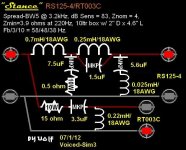
B is a coil placed in series with a cap, and the 2 components are strung across the woofer terminals.
A is the added coil in the 0.25mH position.
Like this attached...
The 1.5uF is something I did not mention, but could also help. I know the values are different, but the layout is as suggested for the woofer, sans the 1.5uF cap.
Wolf
A is the added coil in the 0.25mH position.
Like this attached...
The 1.5uF is something I did not mention, but could also help. I know the values are different, but the layout is as suggested for the woofer, sans the 1.5uF cap.
Wolf
Attachments
As I said, passive for now - active will require amplifiers I cannot currently afford.
The parts for the passive crossover are more expensive than amplifier boards.
The parts for the passive crossover are more expensive than amplifier boards.
Cost is only an issue if you have to buy them.
I've a significant box of old film caps harvested from old equipment and speakers and about 5kg of 16AWG enamelled copper wire on a spool in the garage. passive xovers are much lower cost than going active (I think the OP is in a similar position).
Plywood got a much lower density and therefore resonates much easier than MDF. Plywood is therefore only better than MDF if the enclosure is enforced with ring and/or cross braces.
Density is not an asset.
Your first sentence is an illogical conclusion.
If one has 2 panels of the same stiffness, the denser one (ie heavier) will resonate at a lower frequency than the less dense panel so is more likely to be excited when playing with music.
Due to MDFs lower stiffness it needs more bracing than a proper quality plywood box.
dave
I don’t know which one ICG would choose, but the box that goes lowest probablty does not sound as refined or controlled as the other.
The curve that goes lower breaks the/my rule that the 1st derivative of the FR doesn’t cross zero more than once.
dave
I don't believe these small issues will be a problem.. but if you have the need, an equaliser (old, new, computer based) can help you make adjustments.
The whole point is to be creative and have fun. In the end if you can sit down in front of the system and enjoy the music.
We can only help you make them better. We all have our own experiences and opinions. 2 good designers can make very different design decisions. There are just sooo many compromises that have to be made.
Limited budget/limited experience is part of those set of compromises. What you learn from this one will be applied to your next one.
Keep on truckin'
Density is not an asset.
Your first sentence is an illogical conclusion.
If one has 2 panels of the same stiffness, the denser one (ie heavier) will resonate at a lower frequency than the less dense panel so is more likely to be excited when playing with music.
Due to MDFs lower stiffness it needs more bracing than a proper quality plywood box.
That's not how physics work. Your suggestion was to use a thinner material and no braces. That conclusion is only partly true because a heavier object needs a lot more energy to be moved (vibrate). And the thinner it is, the stronger the vibration. That means, you have to fight vibrations in a frequency range on ply where it's a lot more unpleasant (midrange). If you don't fight it, it gets worse and you are completely ignoring the fact that the membrane movement creating an impulse onto the enclosure and if it's very light you're moving/vibrating the enclosure instead of dispersing it as sound. That 'eats' a lot of an impulse (high amplitude) and you lose on dynamics and precision and not what you want, you want your signal (sound) to be dispersed. A heavy enclosure got a lot more mass inertia and reacts a lot less strong, more energy is dispersed as sound. So yes, density actually is an asset.
There are good reasons to use plywood, esp on a PA for much better handling and less weight on the truck but there are only few advantages you can actually gain at home (design, surface finish, more pleasant to work on, less wear on the tools).
I don’t know which one ICG would choose, but the box that goes lowest probablty does not sound as refined or controlled as the other.
The curve that goes lower breaks the/my rule that the 1st derivative of the FR doesn’t cross zero more than once.
That depends on how well it's designed. But you break your own rule very often yourself because you simulate your speakers with zero inductance resistance and - as we all know - such chokes do not exist. Once you introduce the serial resistance into the simulation, the Qt rises. That may be new to you but that's how it actually is in physics. I've added 0,6 Ohm serial resistance, which is realistic.
Aside from that, both of my simulations cross the zero just once but that doesn't matter anyway because he doesn't want to go as low as possible but his sim already goes too far down and sacrifices a lot of precision and SQ by the (still) high excursion of his mid-woofer, the very low xo to the sub is simply sub-optimal. 😛 😉 🙄
B is a coil placed in series with a cap, and the 2 components are strung across the woofer terminals.
A is the added coil in the 0.25mH position.
Like this attached...
The 1.5uF is something I did not mention, but could also help. I know the values are different, but the layout is as suggested for the woofer, sans the 1.5uF cap.
Wolf
Thanks. But forgive my ignorance - what it the difference between stringing the components across the terminals and stringing them across the speaker wires?
B is a coil placed in series with a cap, and the 2 components are strung across the woofer terminals.
A is the added coil in the 0.25mH position.
Like this attached...
The 1.5uF is something I did not mention, but could also help. I know the values are different, but the layout is as suggested for the woofer, sans the 1.5uF cap.
Wolf
That's OK. Sometimes "across the terminals" just means they are the first components..
The first components in the filter path then?
You don't want the LC at the input of the cabinets to the drivers. This will make a very low impedance at the input and hurt your amplifier. They have to be located after the xover adjacent to the driver.
Later,
Wolf
Later,
Wolf
You don't want the LC at the input of the cabinets to the drivers. This will make a very low impedance at the input and hurt your amplifier. They have to be located after the xover adjacent to the driver.
Later,
Wolf
OK I understand now - thanks.
Your suggestion was to use a thinner material and no braces.
You read wrong. I have notr built or designed a box with no braces.
dave
That conclusion is only partly true because a heavier object needs a lot more energy to be moved (vibrate). And the thinner it is, the stronger the vibration
That is not exactly so. There are other varaibles that affect things.
The idea is to place any (potential) resonance somewhere it will unlikely ever be excited.This means a high frequency where little to no music has high sustained narrowband output at the kind of frequencies to get these excited. Do in effect the box structure is non-resonant.
Thin, stiff material helps. Short spans. Curves. Other tricks.
And if you can get them hiQ they are harder to excite (narrower bandwidth accepting input). More mass just measn you have to fight a lower Q.
More damping in the material also helps. MDF is not really that well damped (it does leak some low level grunge which i guess you could call "damped stuff from the inside”). In a piece of plywood, each transition from one ply to the next is a damping layer. If it is damping at a high frequency it is very effective.
dave
The whole point is to be creative and have fun. In the end if you can sit down in front of the system and enjoy the music.
We can only help you make them better. We all have our own experiences and opinions. 2 good designers can make very different design decisions. There are just sooo many compromises that have to be made.
Limited budget/limited experience is part of those set of compromises. What you learn from this one will be applied to your next one.
Keep on truckin'
Thank you!
But you break your own rule very often yourself because you simulate your speakers with zero inductance resistance and - as we all know - such chokes do not exist
The very nature of the boxes i design means there is a step beyond the sim that takes into account the nature of the highR vents. This has proven to work well over many boxes (i’ve lost count, 100+ at least i’d guess) in practice.
And every driver i sim has the voice coil indictance in it. Its resitance is the Dcr.
dave
- Home
- Loudspeakers
- Multi-Way
- Mini Towers