I'm also hoping that bi-amping highs and lows like this will make it sound louder and clearer without bass distorting the smaller speakers.
hi,
How do you intend to do the bi-amping crossover ?
🙂/sreten.
bjorno said:
Not in my opinion if the prerequisites are followed: A box max 7-8" cube i.e. about 5 L and the use of the given 4-channel BTL Car Radio IC.
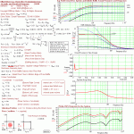
Actually, for this case the ED driver would be wasted. See the picture: 1(1)
b
1(1)
Its a nice graph...but it went over my head.
I don't understand why the elemental designs driver would get less power? Its available in D2 and D4 models. If the D2 was wired in series you'd get 4 ohms, the same as the tang band.
But using the D4 could you not drive each coil with 1 channel, for a total of 32W with the 14.4V NiCad? I don't understand how the TB could get the same amount of power...that chip is bridged internally, and paralleling it won't give you more power if you're stuck with a 4 ohm speaker. Each channel is 4 ohms stable, paralleling them does nothing.
Could the cube be made slightly larger or stuffed with polyfil to make it more suitable. IMO the elemental designs driver is a better overall sub.
I'll get to a few pictures when I find my camera...........bjorno said:
Im curious about the rare 2 1/4" 5W drivers for L & R you mentioned, can you post a picture and what brand?
b
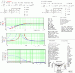
1(2)
Anyway, they have no brand name. I wish I knew more about them. I also wish I had many more of them.
I got 3 of them 9 yrs ago in tech school. They were the "beep" spkr in old Gateway2000 486 computers. However, I noticed immediately that they were above the average 2 inch speaker.
They say 5W 8 ohm (ohm symbol) on the magnet, and it's a small shielded pole magnet. The dust filter is shiny silver plastic on a paper cone. They are more efficient and louder by far than the regular generic 0.5W 2 1/4 spkr and have good treble and better bass (for what little bass they have) The cone moves a lot with music unlike the generic spkrs.
I figured they would make good small loudspeakers, and I'll add piezo tweeters to add more to the highs.
Hi Judtoff,
Maybe over my head too 🙂 when I just took the TS data given for guaranteed and trustworthy at:…
http://www.edesignaudio.com/product_info.php?t=2&products_id=33
…and without more hesitation than the numbers should be valid for series connected coils.
😱 Unfortunately I noticed too late that the TS data given was not consistent and incomplete. See picture 1(1).
The uses of given incorrect data for the ED driver gave an illusion of a much higher load impedance.
The only reason to parallel connect an otherwise unused power stage than allow for 2 Ohm is to gain lower losses (saturation voltage) in the IC transistors and to allow for use of the highest possible supply voltage without activating eventually built in current protection circuits.
The internal voltage loss is about 2 V at max output current= 4 A peak and not more than 16.5V peak is allowed with a 4 Ohm load = 34 W Rms.
The saturation loss + max allowed peak output voltage sums up to 18.5 V which is higher than max allowed supply voltage = 18 V.
So if 18 V is the maximum supply voltage then only 18 – 2 = 16 V is possible to be peak voltage for each half of the output stage and that results in 32 W Rms.
When a driver in box show up impedance lower than 4 Ohm an even larger current could be drawn and both the ED or TB drivers shows lower impedances than 4 ohm at some points even in the suggested 5 L closed box.
Ok for resistive >=4 ohms but not if shooting for performance at the operating point limits with the suggested BTL amp or when using speakers labelled 4 Ohm that occasionally dips down below the Re value due to bad design.
Looking at HA13158A THD graphs I find its obvious that for output powers above 15 W Rms/ channel where the THD skyrockets its possible by using paralleled bridged amplifiers to push this point above 30 W Rms as a real bonus.
b
1(1)
...Its a nice graph...but it went over my head...
Maybe over my head too 🙂 when I just took the TS data given for guaranteed and trustworthy at:…
http://www.edesignaudio.com/product_info.php?t=2&products_id=33
…and without more hesitation than the numbers should be valid for series connected coils.
😱 Unfortunately I noticed too late that the TS data given was not consistent and incomplete. See picture 1(1).
...I don't understand why the elemental designs driver would get less power? Its available in D2 and D4 models. If the D2 was wired in series you'd get 4 ohms, the same as the tang band...
The uses of given incorrect data for the ED driver gave an illusion of a much higher load impedance.
...But using the D4 could you not drive each coil with 1 channel, for a total of 32W with the 14.4V NiCad? I don't understand how the TB could get the same amount of power...that chip is bridged internally, and paralleling it won't give you more power if you're stuck with a 4 ohm speaker...
The only reason to parallel connect an otherwise unused power stage than allow for 2 Ohm is to gain lower losses (saturation voltage) in the IC transistors and to allow for use of the highest possible supply voltage without activating eventually built in current protection circuits.
The internal voltage loss is about 2 V at max output current= 4 A peak and not more than 16.5V peak is allowed with a 4 Ohm load = 34 W Rms.
The saturation loss + max allowed peak output voltage sums up to 18.5 V which is higher than max allowed supply voltage = 18 V.
So if 18 V is the maximum supply voltage then only 18 – 2 = 16 V is possible to be peak voltage for each half of the output stage and that results in 32 W Rms.
When a driver in box show up impedance lower than 4 Ohm an even larger current could be drawn and both the ED or TB drivers shows lower impedances than 4 ohm at some points even in the suggested 5 L closed box.
… Each channel is 4 ohms stable, paralleling them does nothing…
Ok for resistive >=4 ohms but not if shooting for performance at the operating point limits with the suggested BTL amp or when using speakers labelled 4 Ohm that occasionally dips down below the Re value due to bad design.
Looking at HA13158A THD graphs I find its obvious that for output powers above 15 W Rms/ channel where the THD skyrockets its possible by using paralleled bridged amplifiers to push this point above 30 W Rms as a real bonus.
b
1(1)
Attachments
Hmm, I think both subs are great for such a project. However, the ED is more expensive, and larger so that makes the difference.
I want to go ahead, use the 2.25" speakers w/tweeters and 5.25" TB sub. It's a good combo for a small sound system that's portable.
and
Then after I build that one, I want to get a modern car radio DMOS BTL chip of 50 or 52W max/channel. I'd use 3.5" 4 ohm car spkrs for front, and a dual TWO OHM coiled ED 6.5 subwoofer Most of the DMOS output ICs can take 2 ohms BTL with a good heatsink, so dual two ohm coils would make good power. The system as a whole would be louder, but also a bit larger.
I want to go ahead, use the 2.25" speakers w/tweeters and 5.25" TB sub. It's a good combo for a small sound system that's portable.
and
Then after I build that one, I want to get a modern car radio DMOS BTL chip of 50 or 52W max/channel. I'd use 3.5" 4 ohm car spkrs for front, and a dual TWO OHM coiled ED 6.5 subwoofer
Most of the DMOS output ICs can take 2 ohms BTL with a good heatsink, so dual two ohm coils would make good power. The system as a whole would be louder, but also a bit larger.EWorkshop1708 said:Then after I build that one, I want to get a modern car radio DMOS BTL chip of 50 or 52W max/channel. I'd use 3.5" 4 ohm car spkrs for front, and a dual TWO OHM coiled ED 6.5 subwoofer
I would go with a 41hz.com AMP9 and the dual 2ohm version of the ED sub. With two channels parallel per sub @ 1 ohm you should be able to get a respectable amount of power from that small amp with only 12v input.
Thanks for the explanation Bjorno.
Either way, I want to see how this project turns out. It sounds neat lol.
Best of luck to the OP.
Either way, I want to see how this project turns out. It sounds neat lol.
Best of luck to the OP.
theAnonymous1 said:
I would go with a 41hz.com AMP9 and the dual 2ohm version of the ED sub. With two channels parallel per sub @ 1 ohm you should be able to get a respectable amount of power from that small amp with only 12v input.
Very interesting......
I just found a better 2" speaker. Not sure where to get it, but I found it looking around.
http://www.tb-speaker.com/detail/1208_03/w2-748sg.htm
Still 8 ohms, but double the power handling, better frequency range, and no dustcap. Hmm, if I can get these, that reduces my worry of what I have to do if I blow the 2.25" speakers I have already. I may even consider just going with the better speakers instead.
- Status
- Not open for further replies.
- Home
- Loudspeakers
- Subwoofers
- Mini Subwoofer