I did that already see links in reply #12.
The goal for this project is to build a tube phono preamp with work on cheap 48v Power over ethernet adapter. And testing the possibilities of the 6n28b tube.
The goal for this project is to build a tube phono preamp with work on cheap 48v Power over ethernet adapter. And testing the possibilities of the 6n28b tube.
Last edited:
Fair enough - still for the voltages you're using negative feedback equalisation is your only shot at decent performance. Perhaps use an SRRP or white cathode follower output to drive those low line level impedances?
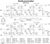
Today i had time to spend with the mini-me 2.
I have changed the schematic to get lower distorsion. From 1.2% to 0.25%.
2nd harm. from -40db to -53db.
Further i gonna make a new PCB. Because i will lower the influence of difference in amplification factor between tubes.
I have changed the schematic to get lower distorsion. From 1.2% to 0.25%.
2nd harm. from -40db to -53db.
Further i gonna make a new PCB. Because i will lower the influence of difference in amplification factor between tubes.
Attachments
Hi,
Nice effort of making a LV valve preamp.
If you don't mind, may I ask why the gridleak resistors are drawn so far away from their grids?
I don't see the point in bypassing the diodes of the cathode of the first stage, have you tried removing them?
Given the low B+ it may be worth a try to use a CCS for the first two stages, it would increase gain and lower distortion. The RIAA network may need some revising though.
Nice work. 😎
Cheers, 😉
I use the same technique with my grid leak resistors as it maximizes the available stage gain (no implicit resistive voltage divider as part of the RIAA network) - I've been doing this since the late 1980s.. I assume Koifarm is using the technique for the same reason. (Have to make sure one does not exceed the maximum allowed grid circuit resistance, at least by much.. 😀 )
Hi,
Never too old to learn. 😀
Grid current flowing through the RIAA network components is no issue then?
Guess we'll have to discuss this one day over "un cornet de frites et une bonne biere", right?
Cheers, 😉
I use the same technique with my grid leak resistors as it maximizes the available stage gain (no implicit resistive voltage divider as part of the RIAA network) - I've been doing this since the late 1980s..
Never too old to learn. 😀
Grid current flowing through the RIAA network components is no issue then?
Guess we'll have to discuss this one day over "un cornet de frites et une bonne biere", right?
Cheers, 😉
Ca Va 😀
(Hasn't caused noise issues so far, IMLE the noise performance is dominated almost entirely by the first stage, and there is a small noise hit implicit in the placement of the resistor at the grid due to the attenuation which might be a couple of dB.)
(Hasn't caused noise issues so far, IMLE the noise performance is dominated almost entirely by the first stage, and there is a small noise hit implicit in the placement of the resistor at the grid due to the attenuation which might be a couple of dB.)
Thanks kevinkr for the explenation.
Frank about the RIAA see the almost straight line at the picture in the first thread.
Removing C21/C24 i still need to try next time. First i need to build a new PCB with different tube setup.
Each 6N28b-v has a slightly different amplication factor. By using the triodes of one tube in the same amp position the difference between channels stays low.
With the setup i have now using the triodes after each other, there is a noticeble difference in amplification between left and right channel( 1,5db).
Hi,
Re: RIAA, I meant should you decide to go from anode resistor to CCS load.
As for the difference in gain, that doesn't come as a surprise. Ideally the valves should be matched as much as possible.
Cheers, 😉
Re: RIAA, I meant should you decide to go from anode resistor to CCS load.
As for the difference in gain, that doesn't come as a surprise. Ideally the valves should be matched as much as possible.
Cheers, 😉
The tubes are probably operating in a region where their mu is inconsistent from sample to sample, I've not seen this issue much in common tubes, but it is an issue with some of the high transconductance types I favor, the key obviously is to stay out of the variable mu region, and with some types matching will be necessary. Operating at somewhat higher plate voltages might help to address this issue, even 100V may make a difference by allowing you to choose an operating point where performance from sample to sample may be more consistent, and linearity will be somewhat better..
Today i tried a new version. With 80v anode voltage, seperate heater supply, other working point, added rumble filter, other tube setup.
And it sounds very good, wide soundstage like the first mini-me, no distorsion, great detail. The final pcb design and schematic will come later. I will make the pcb universal for choice of power supply.
Also i will do some measurements.
And it sounds very good, wide soundstage like the first mini-me, no distorsion, great detail. The final pcb design and schematic will come later. I will make the pcb universal for choice of power supply.
Also i will do some measurements.
Hi Koifarm,
i´m really looking forward to your upgraded version - i like those
small tubes ;-) Great project
Greetings Ulf
i´m really looking forward to your upgraded version - i like those
small tubes ;-) Great project
Greetings Ulf
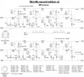
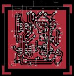
Schematic and PCB layout.
This version you can use your own favourit power supply. For heater i use 24v DC and for anode supply 80v DC regulated.
Distorsion is below 0,1%, amplfication is 325 times.
This version you can use your own favourit power supply. For heater i use 24v DC and for anode supply 80v DC regulated.
Distorsion is below 0,1%, amplfication is 325 times.
Attachments
Last edited:

That must be possible.
Keep in mind that second tube stage grid capacitance is part of the RIAA correction. 6922 tube has other grid capacitance. You need to correct the 470pf(C8/C18) capacitor. Now the 6n16 has about 15x 1.4pf= 21pf capacitance for the 6922 that will be about 30x 3.1pf= 93pf. Try 390pf for 470pf capacitor in first RIAA correction stage.
Keep in mind that second tube stage grid capacitance is part of the RIAA correction. 6922 tube has other grid capacitance. You need to correct the 470pf(C8/C18) capacitor. Now the 6n16 has about 15x 1.4pf= 21pf capacitance for the 6922 that will be about 30x 3.1pf= 93pf. Try 390pf for 470pf capacitor in first RIAA correction stage.
Koifarm, Thanks for the RIAA correction information, the gain and input capacitances would affect the RIAA equalization by about 15%.
I'm expecting the JFET to reduce the s/n by 10db and microphonic effects 20db.
I'm expecting the JFET to reduce the s/n by 10db and microphonic effects 20db.
Last edited:
My plan to build the original mini-me was delayed. Now, I see that 2nd edition v2 is available and maybe I should skip the original, just build the last 2nd edition mini-me.
Looks like 2nd is easier to build but
Can you share your observations on sound quality original mini-me vs. 2nd mini-me ver. 2?
thanks
Looks like 2nd is easier to build but
Can you share your observations on sound quality original mini-me vs. 2nd mini-me ver. 2?
thanks
As in post 31.
http://www.diyaudio.com/forums/anal...-edition-tube-phono-preamp-4.html#post4378989
I still like/use the first edition but that is personal.
Schematic is almost like first mini-me with other tubes and you must ad your own power supply for 24v heater(78L24)and 80v anode supply(TL783).
http://www.diyaudio.com/forums/anal...-edition-tube-phono-preamp-4.html#post4378989
I still like/use the first edition but that is personal.
Schematic is almost like first mini-me with other tubes and you must ad your own power supply for 24v heater(78L24)and 80v anode supply(TL783).
Last edited:
Can one switch easily between mm and mc cartridges? I use both a Denon 103R along with MM cartridges and would like to switch between them.
Quite interested in your mini me as it has quite convenient loading and is versatile.
Quite interested in your mini me as it has quite convenient loading and is versatile.
- Status
- Not open for further replies.
- Home
- Source & Line
- Analogue Source
- Mini-Me second edition tube phono preamp