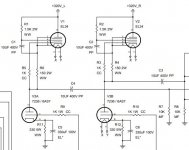
I just finished my build of the Pete Millett low-mu preamp. I haven't started fully testing it just yet, just turned it on a couple of times to make sure nothing caught fire and checked the voltages. My PS is a bit different from the original schematic (I'm using mostly junk box parts) so the B+ into the EL34s is around 300V and that gives me 100V on the 6AS7 plates. The EL34 CCSs are supposed to give 50mA each to the 6AS7, but when I check (measured across cathode resistor and PS resistor) it's around 63mA.
The total current in the PS is 127mA, will the Hammond 10H/125mA choke I'm using be OK with this, or should the CCS (or cathode resistor?) be recalculated for a lower current?
The total current in the PS is 127mA, will the Hammond 10H/125mA choke I'm using be OK with this, or should the CCS (or cathode resistor?) be recalculated for a lower current?
Attachments
It's always a good idea to have some safety margin designed in. Also consider line voltage variation.
Yeah, the choke is the weakest link here when it comes to current. I might reconfigure so it draws a little less HT. The line voltage here is very stable, 235-236 volts with very little variation.
Just change out R6 and R4 to 180 Ω from 150 nominal. At the outset, then 'read' the 6AS7 plate volts; it is going to drop, without changing the 330 Ω cathode ballast resistors out for 390 Ω, each.
But you can do only one channel, and listen to the difference. Who knows, at the loudest volumes you envision, changing out R11, 12 might not even be required. The only criterion will be a compromise between “the sound” and “the quiescent design”.
⋅-⋅-⋅ Just saying, ⋅-⋅-⋅
⋅-=≡ GoatGuy ✓ ≡=-⋅
But you can do only one channel, and listen to the difference. Who knows, at the loudest volumes you envision, changing out R11, 12 might not even be required. The only criterion will be a compromise between “the sound” and “the quiescent design”.
⋅-⋅-⋅ Just saying, ⋅-⋅-⋅
⋅-=≡ GoatGuy ✓ ≡=-⋅
Thanks a lot, GoatGuy! That leaves out my amateur guesswork 🙂
I played it for over an hour today without any big issues. The power transformer gets a bit warm (pulling 5.5A from a 5A heater winding might have something to do with it), so lowering the HT current should help a little and also give the choke some overhead. I've seen that some have had bad hum problems with this circuit, but this is very quiet.
I played it for over an hour today without any big issues. The power transformer gets a bit warm (pulling 5.5A from a 5A heater winding might have something to do with it), so lowering the HT current should help a little and also give the choke some overhead. I've seen that some have had bad hum problems with this circuit, but this is very quiet.
There's no noticeable hum in my amp, even on full volume. I have another 6AS7 and a couple of 6080s so I'm going to try them, maybe I'm just extremely lucky with the tube I have installed.
Great pre amp. The best part is you can swap tubes to 6BX7 or 6BL7 for more gain if needed. (You will need to be able to adjust the CCS current depending on tube, but all you need for that is a switch and a resistor).
I think I get enough gain from the 6AS7, but BL/BX could be fun to try. I have a couple of them already.
I put 27Ω/1W resistors in series with R4/R6 for a total of 177Ω, that lowered the 6AS7 plate voltage down to around 90V. There's 20V on the cathodes now so that would be 60mA current through the 330Ω resistor. I think I might try to up the cathode resistor a little bit, but I don't have the exact values so I have to use series resistors to find the right spot.
I have a 280Ω resistor before the first cap to limit inrush current as I originally planned to use a 5R4, but now that I have a 5V4 I could also try lowering that to raise the overall voltage.
I have a 280Ω resistor before the first cap to limit inrush current as I originally planned to use a 5R4, but now that I have a 5V4 I could also try lowering that to raise the overall voltage.
Last edited:
I swapped the 150R (R4/R6) resistors for 220R/5W, I'm at around 83-85V on the 6AS7 plates and 55mA current now. Those 220R/5W resistors get pretty toasty, even with only 0.7W dissipation. The lower current raised the B+ to 310V so I'm just keeping the 280R inrush resistor. The choke should be a bit happier now at least, I'll check how it sounds later today.
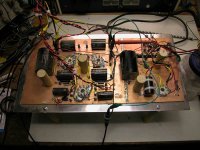
Did you guy build your amps on the copper plate like Pete did?. I'm wondering if that is the source of my hum.
I just used a perforated steel sheet I had for my top plate. I read about hum issues when I started so I had that in mind when I did the wiring. Did you use the copper plate? Do you have a picture of your layout?
Here is a pic of the pre and link to a thread of the guy who built it.
Pete Millett Low-Mu Triode Preamp
Pete Millett Low-Mu Triode Preamp
Attachments
I can't help much sadly, I would suspect it's a grounding issue, but I wouldn't know where to start looking. If it were me, I'd probably rebuild it with the grounding scheme I'm familiar with 😀 I use a star ground and wire all the grounds separately to the "master" star point in the power supply.
Did you guy build your amps on the copper plate like Pete did?. I'm wondering if that is the source of my hum.
Isn't that more of an issue where you have signal transformers? Where magnetic currents can induce hum in the transformers. ?
Have you proper elevation of the heaters? Could it be the EL34's heater injecting hum into it's cathodes?
The heaters are referenced to +45Vdc, to avoid exceeding the 100V heater-cathode rating of the EL34s. It should also lower any noise from the 6AS7.
The heater to cathode rating of 6AS7 is 300V. I would try placing the heaters to a potential at least 10volts above the EL34s cathode.
Hum can come from free electrons surrounding the heater element. These electrons will be drawn to the cathode if the potential there is positive relative to heater. If the heaters are AC the electrons will be drawn with the AC frequency modulation. 50 or 60 Hz depending on where.
Hum can come from free electrons surrounding the heater element. These electrons will be drawn to the cathode if the potential there is positive relative to heater. If the heaters are AC the electrons will be drawn with the AC frequency modulation. 50 or 60 Hz depending on where.
- Home
- Amplifiers
- Tubes / Valves
- Millett 6AS7 preamp CCS current