Hello,
You may find here attached:
- the profile of a 150Hz Le Cléac'h for the FE206E (Fc = 150Hz)
-the contour of a half petal to build a "gramophone type" horn having 9 petals.
Best regards from Paris, France
Jean-Michel Le Cléac'h
Bonjour M. Le Cléac'h,
Merci beaucoup pour votre aide. Vous êtes très généreux.
Regards
Kevin
Hey Kevin,
Move the file to the Hornresp importfolder and open it with the program. The you will have something to play around with. It´s a model of a 140Hz tractrix driven by Fane 8M Studio.
Move the file to the Hornresp importfolder and open it with the program. The you will have something to play around with. It´s a model of a 140Hz tractrix driven by Fane 8M Studio.
You may find here attached:
- the profile of a 150Hz Le Cléac'h for the FE206E (Fc = 150Hz)
Hi Jean-Michel,
I am trying to understand why the profile dimensions in your attachment are somewhat different to those calculated by Hornresp 🙂.
Are you using your improved method to calculate the "isophase wavefront" surface areas? Also, what value of T do you assume?
Your data indicates:
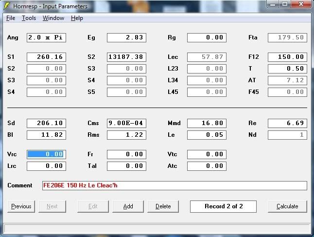
1. A minimum radius of 91.0 mm - giving a Hornresp equivalent S1 = 260.16 sq cm.
2. A maximum radius of 648.0 mm - giving a Hornresp equivalent S2 = 13191.67 sq cm.
3. A maximum axial length of 578.7 mm - giving a Hornresp equivalent L12 = 57.87 cm.
Using the above S1 and S2 values in Hornresp, the closest I can get to your results is to set T = 0.48 giving L12 = 58.37 cm and Fta = 177.77 degrees.
I would appreciate any comments that you may have - I assume that you are not using T = 0.48 in your design?
Kind regards,
David
Move the file to the Hornresp importfolder
Forgot the attachment:
Attachments
Hi! Here's me again!
Is it possible to make that for such driver:
Technische gegevens:
201 mm Breitbandlautsprecher,
78-11000 Hz Übertragungsbereich,
96 dB Kennschalldruck,
19 mm Schwingspule,
Thiele-Small Parameter:
Nennimpedanz/Gleichstromwiderstand: 4,7 / 6 Ohm
Fs: 78 Hz
Qms: 7.08
Qes: 1,1
Qts: 0,97
Vas: 39 Liter
Sd: 224 cm²
BL: 3,5 N/A
Xmax: 1,5mm
Cms= 0,56 mm/N
Mms= 7,4 g
Rms= 0,51 kg/s
It is Saba Greencone. I saw someone put it in oris horn and Khorn bas with reportedly good result.
Learn Hornresp and you will find it is acceptable.
Was hopin' to take advantage of your kindness...😀
Anyway, thank's! Will manage somehow.😎
Learn Hornresp and you will find it is acceptable.
Hi Lars,
Thanks for the files to work with. I will be firing up Hornresp over the next few days and trying to wrap my head around it some more (a lot of family obligations lately). I appreciate your input and hope at one point I'll understand enough to contribute some how.
Kevin
Hi Jean-Michel,
I am trying to understand why the profile dimensions in your attachment are somewhat different to those calculated by Hornresp 🙂.
Are you using your improved method to calculate the "isophase wavefront" surface areas? Also, what value of T do you assume?
Your data indicates:
1. A minimum radius of 91.0 mm - giving a Hornresp equivalent S1 = 260.16 sq cm.
2. A maximum radius of 648.0 mm - giving a Hornresp equivalent S2 = 13191.67 sq cm.
3. A maximum axial length of 578.7 mm - giving a Hornresp equivalent L12 = 57.87 cm.
Using the above S1 and S2 values in Hornresp, the closest I can get to your results is to set T = 0.48 giving L12 = 58.37 cm and Fta = 177.77 degrees.
I would appreciate any comments that you may have - I assume that you are not using T = 0.48 in your design?
Kind regards,
David
Hi Jean-Michel,
Further to my message above, I have now double-checked and confirmed that Hornresp generates the same results as your 2007 "improved method" spreadsheet for an axisymmetric Le Cléac'h horn. I am now guessing that you are in fact probably using a T value somewhere near 0.48 in your design 🙂. Is this done perhaps, to set a specific flare tangent angle at the horn throat, or alternatively, to ensure that the horn is at least a quarter of a wavelength long at the 150 Hz flare cutoff frequency?
For a petal horn it seems that you set the regular polygon "inradius" equal to the axisymmetric horn radius, meaning that for a 9 petal horn, areas are increased by a factor of 9 / Pi * Tan(Pi / 9) or approximately 1.04. This will reduce the theoretical cutoff frequency of the horn by a small amount.
Hornresp uses the generally accepted method of making the area of the regular polygon equal to the area of the axisymmetric horn at the same point on the axis, which explains the differences I am seeing in our results.
Do you have a specific reason for increasing the cross-sectional areas in your petal horns above those for an equivalent axisymmetric horn? The only thing I can think of is that with your technique, the planar length of the petal becomes the same as the length of the axisymmetric profile curve, meaning that separate additional calculations are not required in your spreadsheet 🙂.
As always, any comments would be appreciated.
Kind regards,
David
Hello david,
I used T=0.5 (Fc = 150Hz) to calculate this horn as my experience tells me that for cone loudspeakers, a lower T value than the ones used for compression drivers can help, specially with horns of very low cut-off that will be used with a high-pass crossover having a F-3dB ver near of the Fc of the horn.
By times I recommand also T=0 for horns having Fc lower than 200Hz as this leads to a reduced width of the frequency interval inside which the reactance is non negligeible, thus the possible use of a high slope high-pass crossover set at a F-3dB very near of the Fc of the horn.
Best regards from Paris, France
Jean-Michel Le Cléac'h
Hi Jean-Michel,
I am trying to understand why the profile dimensions in your attachment are somewhat different to those calculated by Hornresp 🙂.
Are you using your improved method to calculate the "isophase wavefront" surface areas? Also, what value of T do you assume?
Your data indicates:
1. A minimum radius of 91.0 mm - giving a Hornresp equivalent S1 = 260.16 sq cm.
2. A maximum radius of 648.0 mm - giving a Hornresp equivalent S2 = 13191.67 sq cm.
3. A maximum axial length of 578.7 mm - giving a Hornresp equivalent L12 = 57.87 cm.
Using the above S1 and S2 values in Hornresp, the closest I can get to your results is to set T = 0.48 giving L12 = 58.37 cm and Fta = 177.77 degrees.
I would appreciate any comments that you may have - I assume that you are not using T = 0.48 in your design?
Kind regards,
David
Hello David,
The multifacets ("petals horn") version is a generalization of a pre-existing "square horn" version of my spreadsheet.
That "square horn" version was intended to be used only for the calculation of the part of the horn near the mouth.
I have (and give to whom needs it) another spreadsheet to calculate an adaptator from round to rectangular (square being a special case) which can be used to calculate the part of the horn near the loudspeaker.
I found much more convenient in that case (when the throat is square) to give the length of the edge of the square. Then when modifying the spreadsheet for the petals version I kept the same principle.
Best regards from Paris, France
Jean-Michel Le Cléac'h
Hi Jean-Michel,
Further to my message above, I have now double-checked and confirmed that Hornresp generates the same results as your 2007 "improved method" spreadsheet for an axisymmetric Le Cléac'h horn. I am now guessing that you are in fact probably using a T value somewhere near 0.48 in your design 🙂. Is this done perhaps, to set a specific flare tangent angle at the horn throat, or alternatively, to ensure that the horn is at least a quarter of a wavelength long at the 150 Hz flare cutoff frequency?
For a petal horn it seems that you set the regular polygon "inradius" equal to the axisymmetric horn radius, meaning that for a 9 petal horn, areas are increased by a factor of 9 / Pi * Tan(Pi / 9) or approximately 1.04. This will reduce the theoretical cutoff frequency of the horn by a small amount.
Hornresp uses the generally accepted method of making the area of the regular polygon equal to the area of the axisymmetric horn at the same point on the axis, which explains the differences I am seeing in our results.
Do you have a specific reason for increasing the cross-sectional areas in your petal horns above those for an equivalent axisymmetric horn? The only thing I can think of is that with your technique, the planar length of the petal becomes the same as the length of the axisymmetric profile curve, meaning that separate additional calculations are not required in your spreadsheet 🙂.
As always, any comments would be appreciated.
Kind regards,
David
Thanks Jean-Michel, for your comments.
As always, they are very interesting.
Kind regards,
David
As always, they are very interesting.
Kind regards,
David
Back from the depths
I want to keep this as direct as possible, even though I'm ridiculously long winded, so I'll state what I think is my biggest dilemma first:
How is Martin Seddon of Azurahorn modeling a 160 Hz Le Cléac’h horn profile for a 8" driver with only a 37 inch mouth and 18 inches in length? He states on his website the specifics for his 160Hz horn as:
"This is a large horn with 950mm (about 37 inches) mouth. The axial length is 450mm (about 18 inches) when made for 8” Lowthers."
and further...
(the)"flare rate is 160Hz at 0.8 T factor calculated from a 1.5” throat size"
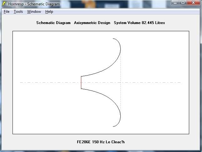
The reason I am asking this question is because when I requested help in modeling a 150 Hz Le Cléac’h profile to use to create a horn for my Fostex 206e speakers a few months ago, and Jean-Michel was kind enough to post a text file with dimensions to use, it did not register with me that this was a horn that would measure over 50 inches in diameter, or as Lars put it 126cm. I didn't do the math. This was mainly because I was so excited that I had something to work with, and also because I assumed the size of the horn wouldn't be that much different from the 160 Azura which I had looked at previously, read reviews of that mentioned its dimensions (as linked to on the first page of this thread) and also had converted the dimensions of myself to be about 37 inches.
So when after a week or so had gone by after Jean-Michel's post, and I sat down to start to try and draw out a template to make a horn based on the text file he posted I realized a few things. The first being that the last dimension in the file which is a 603.1mm radius ( 47 inch diameter) was not what I expected. Then after further investigation I realized it wasn't even the largest dimension in the profile. That turned out to be a 648mm radius, or over 51 inches in diameter! After some head scratching I realized the non-progressive order in the diameters of the profile toward the end of the file was because Jean-Michel's spreadsheet must be modeling the profile of the horn to what I understood as being a full 360 degrees at the mouth. Still I didn't understand the huge difference in overall size from the Azura horn.
Rather than come back and ask for more handouts, I decided I would have to sit down and try to get a grasp on things by trying again to learn Hornresp. I figured if I could use the basic information from this thread discussing how the 150Hz profile was created, and reproduce the results of the file that Jean-Michel had posted, then I might also be able to recreate the 160Hz profile Martin was using on the 160 Azura, understand a little about Hornresp and have a profile for a horn that might physically integrate into my humble listening area.
The learning curve with Hornresp wasn't a complete nightmare 😱. I wish I had better luck with Google and had hit this Hornresp Kickstart article Free Speaker Plans - Free Speaker Plans ? View topic - Horn resp for beginnersbefore rather than after I worked through most of it. I sort of stumbled through the included Help file instead and eventually discovered that Hornresp would calculate most of the speaker parameters it needed for me based on minimal T/S inputs. The one thing I could not come up with was a "Le" parameter because all the data sheets I found on the driver listed it as "n/a". I researched other similar 8" Fostex drivers including the replacement 206en and had to settle for putting in an average specification of .05 since I couldn't enter 0. I digress.
All of this didn't really seem to matter since the profile of the horn and how it was modeled seemed based on the inputs on the top half of the Hornresp window. Once I was able to understand the inputs for the throat area and mouth area, where they were entered to model a front horn, how to tell Hornresp to calculate the Le Cléac’h profile set the cutoff frequency and "T" or flare parameter I was pretty much set and could get profiles to calculate.
Profiles that didn't make sense to me. But that was because I didn't understand that Hornresp wasn't calculating the profile to a full 360 degrees at the mouth like Jean-Michel's spreadsheet had. I had followed Jean-Michel's advice I found in another thread asking for help with modeling his horn profile in Hornresp and noted that he prescribed a maximum figure allowable for the S2 field in order to get a fuller modeled mouth on the horn that rolled back at the edges. Once I realized the difference was how far Hornresp was actually modeling the mouth, I was able to reference key points in the horn flare at almost identical distances from the throat and confirm that the profile I had modeled in Hornresp did in fact look the same as Jean-Michel's.
These were my inputs:
The calculated profile:
I have a text file that I exported with dimensions from Hornresp, but I wasn't sure how to upload and link it since Photobucket only seems to allow for media. I also had questions as to whether I chose the correct settings in the Horn cross section dimensions dialogue box. The Height and Width fields seemed to change automatically based on inputs for the horn profile fields. I couldn't figure out why or how I should change those fields. The increment field was self explanatory. However, I was unclear on what should be selected in the width flare field. I chose Uni rather than Con or Exp as I thought I wasn't modeling a Conical or Exponential horn (stab in the dark). Even the Kickstart article didn't enlighten me here. Either way the output didn't seem to change...or maybe I was just too tired to realize it had.
SO WHAT?!!!
Well I have tried everything I can think of to get a horn profile with dimensions somewhere close to the advertised size of the Azura 160. I tried changing the 150 Hz throat area and T factor to start with, and also played with limiting the mouth area. I gave up on the 150 hz cutoff and switched to 160Hz. I used the .8 T factor Martin mentions on his website. I tried different throat areas again since he was using a different driver to begin with and didn't publish the throat area data. I played with the mouth area again, thinking that perhaps that was how he was limiting the size of the horn and the different T factor might maintain the fuller modeled profile, to the extent of calculating the area of a 37 inch mouth and setting the S2 parameter to that figure. The resulting profile ended up incomplete compared to the images of the 160 horns on his website which definitely have mouths with rolled edges. I realized I had missed the fact that he states the horn was modeled from a 1.5" throat. I assumed this was to pair it with compression drivers and calculated a radius in cm along with the new throat area and recalculated the horn. I could only assume he was cutting the horn off where it was the proper diameter to match the area needed for an 8 inch driver, still after looking over the data output it didn't seem close. At one point I thought perhaps he was referring to the mouth dimension as the point where the horn no longer flares forward and out, and that he wasn't counting the backward rolling of the mouth lip in his dimensions. Another look at the post I had referenced by an owner of the Azura 160 shot that down with his mention of the overall size only being 37 inches in diameter. My final stab was that perhaps he wasn't modeling the horn in half space as I thought it was supposed to be (2.0 X Pi?) but instead quarter space (1.0 X Pi?). I tried this as well and came up with a smaller diameter close to his horn, but the horn was quite a bit longer than it should be. This all made me have more doubts about what space I was supposed to be modeling this horn in. What am I missing?
I want to keep this as direct as possible, even though I'm ridiculously long winded, so I'll state what I think is my biggest dilemma first:
How is Martin Seddon of Azurahorn modeling a 160 Hz Le Cléac’h horn profile for a 8" driver with only a 37 inch mouth and 18 inches in length? He states on his website the specifics for his 160Hz horn as:
"This is a large horn with 950mm (about 37 inches) mouth. The axial length is 450mm (about 18 inches) when made for 8” Lowthers."
and further...
(the)"flare rate is 160Hz at 0.8 T factor calculated from a 1.5” throat size"
The reason I am asking this question is because when I requested help in modeling a 150 Hz Le Cléac’h profile to use to create a horn for my Fostex 206e speakers a few months ago, and Jean-Michel was kind enough to post a text file with dimensions to use, it did not register with me that this was a horn that would measure over 50 inches in diameter, or as Lars put it 126cm. I didn't do the math. This was mainly because I was so excited that I had something to work with, and also because I assumed the size of the horn wouldn't be that much different from the 160 Azura which I had looked at previously, read reviews of that mentioned its dimensions (as linked to on the first page of this thread) and also had converted the dimensions of myself to be about 37 inches.
So when after a week or so had gone by after Jean-Michel's post, and I sat down to start to try and draw out a template to make a horn based on the text file he posted I realized a few things. The first being that the last dimension in the file which is a 603.1mm radius ( 47 inch diameter) was not what I expected. Then after further investigation I realized it wasn't even the largest dimension in the profile. That turned out to be a 648mm radius, or over 51 inches in diameter! After some head scratching I realized the non-progressive order in the diameters of the profile toward the end of the file was because Jean-Michel's spreadsheet must be modeling the profile of the horn to what I understood as being a full 360 degrees at the mouth. Still I didn't understand the huge difference in overall size from the Azura horn.
Rather than come back and ask for more handouts, I decided I would have to sit down and try to get a grasp on things by trying again to learn Hornresp. I figured if I could use the basic information from this thread discussing how the 150Hz profile was created, and reproduce the results of the file that Jean-Michel had posted, then I might also be able to recreate the 160Hz profile Martin was using on the 160 Azura, understand a little about Hornresp and have a profile for a horn that might physically integrate into my humble listening area.
The learning curve with Hornresp wasn't a complete nightmare 😱. I wish I had better luck with Google and had hit this Hornresp Kickstart article Free Speaker Plans - Free Speaker Plans ? View topic - Horn resp for beginnersbefore rather than after I worked through most of it. I sort of stumbled through the included Help file instead and eventually discovered that Hornresp would calculate most of the speaker parameters it needed for me based on minimal T/S inputs. The one thing I could not come up with was a "Le" parameter because all the data sheets I found on the driver listed it as "n/a". I researched other similar 8" Fostex drivers including the replacement 206en and had to settle for putting in an average specification of .05 since I couldn't enter 0. I digress.
All of this didn't really seem to matter since the profile of the horn and how it was modeled seemed based on the inputs on the top half of the Hornresp window. Once I was able to understand the inputs for the throat area and mouth area, where they were entered to model a front horn, how to tell Hornresp to calculate the Le Cléac’h profile set the cutoff frequency and "T" or flare parameter I was pretty much set and could get profiles to calculate.
Profiles that didn't make sense to me. But that was because I didn't understand that Hornresp wasn't calculating the profile to a full 360 degrees at the mouth like Jean-Michel's spreadsheet had. I had followed Jean-Michel's advice I found in another thread asking for help with modeling his horn profile in Hornresp and noted that he prescribed a maximum figure allowable for the S2 field in order to get a fuller modeled mouth on the horn that rolled back at the edges. Once I realized the difference was how far Hornresp was actually modeling the mouth, I was able to reference key points in the horn flare at almost identical distances from the throat and confirm that the profile I had modeled in Hornresp did in fact look the same as Jean-Michel's.
These were my inputs:
The calculated profile:
I have a text file that I exported with dimensions from Hornresp, but I wasn't sure how to upload and link it since Photobucket only seems to allow for media. I also had questions as to whether I chose the correct settings in the Horn cross section dimensions dialogue box. The Height and Width fields seemed to change automatically based on inputs for the horn profile fields. I couldn't figure out why or how I should change those fields. The increment field was self explanatory. However, I was unclear on what should be selected in the width flare field. I chose Uni rather than Con or Exp as I thought I wasn't modeling a Conical or Exponential horn (stab in the dark). Even the Kickstart article didn't enlighten me here. Either way the output didn't seem to change...or maybe I was just too tired to realize it had.
SO WHAT?!!!
Well I have tried everything I can think of to get a horn profile with dimensions somewhere close to the advertised size of the Azura 160. I tried changing the 150 Hz throat area and T factor to start with, and also played with limiting the mouth area. I gave up on the 150 hz cutoff and switched to 160Hz. I used the .8 T factor Martin mentions on his website. I tried different throat areas again since he was using a different driver to begin with and didn't publish the throat area data. I played with the mouth area again, thinking that perhaps that was how he was limiting the size of the horn and the different T factor might maintain the fuller modeled profile, to the extent of calculating the area of a 37 inch mouth and setting the S2 parameter to that figure. The resulting profile ended up incomplete compared to the images of the 160 horns on his website which definitely have mouths with rolled edges. I realized I had missed the fact that he states the horn was modeled from a 1.5" throat. I assumed this was to pair it with compression drivers and calculated a radius in cm along with the new throat area and recalculated the horn. I could only assume he was cutting the horn off where it was the proper diameter to match the area needed for an 8 inch driver, still after looking over the data output it didn't seem close. At one point I thought perhaps he was referring to the mouth dimension as the point where the horn no longer flares forward and out, and that he wasn't counting the backward rolling of the mouth lip in his dimensions. Another look at the post I had referenced by an owner of the Azura 160 shot that down with his mention of the overall size only being 37 inches in diameter. My final stab was that perhaps he wasn't modeling the horn in half space as I thought it was supposed to be (2.0 X Pi?) but instead quarter space (1.0 X Pi?). I tried this as well and came up with a smaller diameter close to his horn, but the horn was quite a bit longer than it should be. This all made me have more doubts about what space I was supposed to be modeling this horn in. What am I missing?
It should be clear to anyone that the Azuras doesn´t have a 180 degree rollback. Just adjust Fta to a lower value. Try something like 100-120 degrees instead and you will arrive at the Azura-dimensions.
chromenuts,
You have made more progress on this than I have. I've been wishing to gain the confidence with Hornresp to do as you are, and design my own Le Cleach horn for my old FE 206's.
Keep hammering at it, and Ill keep learning at your feet!
I've been investigating other profiles, and hybrids too, in an effort to keep WAF in the range of " Ok, you can bring that into the house ".
Good luck.
John
It should be clear to anyone that the Azuras doesn´t have a 180 degree rollback. Just adjust Fta to a lower value. Try something like 100-120 degrees instead and you will arrive at the Azura-dimensions.
Hi Lars,
My mention of the rolled lip on the mouth of the Azura 160 wasn't to imply that it's profile had been modeled a full 180 degrees and Martin's horn produced from that data. It was simply an observation that I made after attempting to "reverse engineer" a profile that would mimic his horn with the data he made available on his website. I was trying to obtain the 950mm or approximate 37 inch mouth that he specifies and also obtain a similar rollback at the mouth of my model that looked to be in line with what he was producing.
My assumption was that the mouth area in S2 should be held at whatever area I calculated a 37 inch circle to have. Unfortunately when I did this and plugged in the other parameters that he provides I was not able to obtain any rollback at the mouth that could resemble what he has pictured on his website. The actual results of this first attempt only gave me an Fta of 94.91 degrees which to my eyes and mind couldn't be what he was producing. I was using a S1 of 11.4 to provide a 1.5 inch throat and his specified T parameter of .8 for this model.
Measuring back his specified 450mm length from the furthest point in my horn profile from the mouth put me at 532.5 mm which results in an approximate 210mm throat area for the driver. This is a bit smaller than what I had been using as Jean-Michel's reference to try modeling the 150Hz profile, but I suppose a slight adjustment could be made to cut the horn profile closer to the mouth if desired to gain a larger throat area. That appears to be how Martin is building his horns and then casting the driver mounting flanges on to the them afterward.
I have tried adjusting the mouth area to gain a fuller profile of the horn, or as you stated a larger Fta. This seemed to be the only way I could considerably affect the Fta and the diameter of the horn. Obviously the more I gained in profile extension the larger the horn diameter became.
As an example, I went back and modeled as close as I could get to a Fta of 100 and 120 degrees as you suggested. I used the same inputs as before except for the change to S2 that would deliver the desired Fta. I ended up with a diameter just short of 39 inches for an Fta of 100.65, and just short of 43 inches for an Fta of 120.15. The throat area is maintained in these profiles given the stated 450mm length of the horn.
I suppose the real dilemma is that I have never seen one of these Azura horns in person and measured it, so there is no way of knowing their exact diameter. Nor can I know for sure the Fta that they are modeled with. All I can do is assume that the diameter dimension is as specified and estimate the Fta angle the horn is modeled to visually from the pictures on the website. To my eye I could easily imagine the Fta of the Azura at 100 or 120 degrees, but I can't maintain the actual horn diameter he specifies.
I suppose it will boil down to compromise if no one can point out something I am doing wrong. I still have other considerations to take into account like the fact that Jean-Michel recommended a T factor of .5 to begin with for cone speakers like the 206e. I also haven't begun to consider other aspects of the design such as a rear chamber or become familiar with using the analysis aspects of Hornresp to judge performance of the horn.
Thanks for your feedback.
chromenuts,
I've been investigating other profiles, and hybrids too, in an effort to keep WAF in the range of " Ok, you can bring that into the house ".
Hi John
I have done this as well. I modeled a Tratrix profile in Hornresp for the 206e and the difference in size is amazing as Lars has previously stated. I'm not too obsessed with the WAF approval however, and the feedback about the Le Cléac’h profile is motivating me in that direction. I figure its easier to ask forgiveness than get permission when it comes to my hobbies.
Thanks for your words of support.
Kevin
- Status
- Not open for further replies.
- Home
- Loudspeakers
- Multi-Way
- Midrange Horn for FE206e