Missing Ingrediants
If you want good output at the HF end, use a phase plug and tweak the front cavity resonance to provide a boost there.
I have not read all the posts here; maybe this has already been addressed.
While challenging, a one decade bandwidth can be achieved without performance sacrifice if the horn design regime is rigorously pursued. Here driver selection is key limiting factor.
Good Luck,
WHG
Do you think there are two issues, one near 500 (rear chamber), and one at 550 (mouth)?
Some suggest sizing the rear chamber for reactance annulling. This can be fiddly to get right for the benefit of HD, if that is important, but it takes an impedance plot to tune well.. Personally I like to consider group delay as well, something for later maybe.
The rear chamber appears to be affecting the highs.
It looks like it. Someone suggested the horn might be rolling off at 500ish Hz and then a resonance might be picking up lower. So one path I'm exploring is further work on reactance annulling to try and bring the resonance up in frequency so the "peak" seen around 380ish moves up and covers the trough around 550Hz.
Can you think in a way I could use the last results (with the foam panels) into a practical solution?
Could you replace the microphone with a connection to the speaker which is fed from a larger series resistance?Unfortunately I don't have the connectors yet to be able to measure the impedance peak,
My confidence in exploiting a resonance increases when I can show that it follows the primary horn mode, which is why I try to identify individual elements that are doing their own thing. This tends to rule out relying on resonances in the highs, and can lead to enforcing what's reasonable for a non axissymmetrical shape, but at some point it may also reach the point where compromises are worth considering. I can see symmetry in the top and bottom panels as reasonable for this single horn unit although it is not set in stone.a resonance might be picking up lower.
In deference to whgeiger's comments, the compromises in a lower midrange horn are considerable but not insurmountable.
It has been shown that following a shortened horn with a secondary flare at sharply twice the angle can lead to a good compromise without adding too much in length (a minor rounding at the transition like you added at at the mouth might still be good for the highs). This was behind my suggestion for baffling above and below. A reflection can result but pattern control can be better so this could result in a reasonable compromise.
The better angle for this might be 60 degrees. Maybe the sides could be angled back ala LeCleach as a further consideration. I feel that size is often compromised but simply causes other problems if taken too far. Notwithstanding the precision needed in a tweeter device, I think the lower midrange is the hardest to do well.
Last edited:
If you want good output at the HF end, use a phase plug and tweak the front cavity resonance to provide a boost there.
I have not read all the posts here; maybe this has already been addressed.
While challenging, a one decade bandwidth can be achieved without performance sacrifice if the horn design regime is rigorously pursued. Here driver selection is key limiting factor.
Good Luck,
WHG
Hey whgeiger. Thanks for joining.
The HF was discussed a while back, when I was still using the bare cone, and a 4" dustcap glued to the 5" cone was suggested as an easier path than the phase plug. These last measurements are with the dustcap and a reduced throat. Things did improve with dustcap vs without in that the gently rolling off response in the higher frequencies was replaced with sustained response until mass rolloff shows up. And when it does, it shows its effect big time. Hence the steep rolloff past 1.8kHz. I was hoping for a xo point around 2.2kHz, which is not going to happen with this setup. Probably 2kHz won't fly either.
But lately my focus has been more on the lower end of the response. I was surprised by the dip around 470Hz. My plan was to use this horn from 400Hz and designed it with fc of 200Hz to be on the safe side...but I'm not 😱. So I'm focusing on solving this first. Seems better tunning of the rear chamber and a larger mouth for my next prototype are paths to be pursued.
What do you think?
Horn Tweaks
470 hz dip: SWAG 9" dia. circular cavity resonance (maybe the back-box diameter or equivalent average if square). N.B., Triangular yields a larger dimensional variance.
To retain the horn function as [F] -> [Fc] , horn length ->[c]/ [Fc]/4 and mouth perimeter -> [c]/[Fc]. Tweak neck flare, and back-box volume and geometry.
Nix the big dust cap and use a phase plug to tweak compression ratio [Sd]/[St]and front cavity volume for the high end.
See Beranek Acoustics (1993) pp 283/284 for some details.
https://monoskop.org/images/f/f1/Beranek_Leo_L_Acoustics_no_OCR.pdf
At approximately just beyond the dust cap perimeter, should be the second node of front cavity resonance (standing wave), place the phase plug annulus there.
Regards,
WHG
whgeiger,
While theory would point you towards using a phase plug for any horn I question that when we are talking about using an existing cone driver that was never designed for such use. Whether the cone can handle the loading an not deform under load is a real question which would be directly related to the ratio of cone area to phase plug initial opening. A typical compression driver ratio is 10:1 and I don't think any standard paper cone driver would handle that well. The other problem I see is that you will now start with a much smaller initial area and using the same expansion rate to keep the lowest frequency response will require a much longer horn to have the same low frequency cutoff without some real response boost and consequently extra power output from a power amplifier to boost those low frequencies. Using a hyperbolic expansion with a T value of 0.6 or above will help to support the lowest frequencies with a subsequent reduction in high frequency response. We do have to take into account the very low power output of the amplifier that Lewinsky has stated he wants to use for this mid-range horn. The reality in my eyes is that at this extremely low power output he should be looking at using a 2" exit compression driver and not a cone that would require much more power amplifier output.
While theory would point you towards using a phase plug for any horn I question that when we are talking about using an existing cone driver that was never designed for such use. Whether the cone can handle the loading an not deform under load is a real question which would be directly related to the ratio of cone area to phase plug initial opening. A typical compression driver ratio is 10:1 and I don't think any standard paper cone driver would handle that well. The other problem I see is that you will now start with a much smaller initial area and using the same expansion rate to keep the lowest frequency response will require a much longer horn to have the same low frequency cutoff without some real response boost and consequently extra power output from a power amplifier to boost those low frequencies. Using a hyperbolic expansion with a T value of 0.6 or above will help to support the lowest frequencies with a subsequent reduction in high frequency response. We do have to take into account the very low power output of the amplifier that Lewinsky has stated he wants to use for this mid-range horn. The reality in my eyes is that at this extremely low power output he should be looking at using a 2" exit compression driver and not a cone that would require much more power amplifier output.
All very valid points, and I also brought up the question about amplifier type a few posts ago. Maybe the amplifier has not been purchased yet ?
Getting back to the response anomaly, I think it's at least partially inherent in the driver itself. I also think the horn has shifted said anomaly up in frequency a bit. From the start, I really didn't think a conventional square mouth tractrix would be ideal for this driver. It's just not the right kind of driver. Bruce Edgar had better luck with this type of driver suing a much larger mouth than what at first appears optimal. It can however, be successfully horn loaded, as it was first brought to my attention several years ago by a gentlemen ( "PK") who used it in a very large conical type horn. Addressing the driver, I would wrap the 4 frame support ribs with a generous helping of mortite. I would use a large mouthed waveguide type of horn with both top and bottom slant boards covered in felt. I would leave the back wave of the driver open to start, and then experiment with different size/shapes/styles of back wave enclosures, if need be. I would terminate the "Horn" exactly at 90 degrees, smoothing terminating into a flat baffle board which would be extremely mass loaded. This is an excellent driver, and probably will come to life with 25-30 watts of pure Class A power.
Getting back to the response anomaly, I think it's at least partially inherent in the driver itself. I also think the horn has shifted said anomaly up in frequency a bit. From the start, I really didn't think a conventional square mouth tractrix would be ideal for this driver. It's just not the right kind of driver. Bruce Edgar had better luck with this type of driver suing a much larger mouth than what at first appears optimal. It can however, be successfully horn loaded, as it was first brought to my attention several years ago by a gentlemen ( "PK") who used it in a very large conical type horn. Addressing the driver, I would wrap the 4 frame support ribs with a generous helping of mortite. I would use a large mouthed waveguide type of horn with both top and bottom slant boards covered in felt. I would leave the back wave of the driver open to start, and then experiment with different size/shapes/styles of back wave enclosures, if need be. I would terminate the "Horn" exactly at 90 degrees, smoothing terminating into a flat baffle board which would be extremely mass loaded. This is an excellent driver, and probably will come to life with 25-30 watts of pure Class A power.
It has been shown that following a shortened horn with a secondary flare at sharply twice the angle can lead to a good compromise without adding too much in length (a minor rounding at the transition like you added at at the mouth might still be good for the highs). This was behind my suggestion for baffling above and below. A reflection can result but pattern control can be better so this could result in a reasonable compromise.
The better angle for this might be 60 degrees. Maybe the sides could be angled back ala LeCleach as a further consideration. I feel that size is often compromised but simply causes other problems if taken too far. Notwithstanding the precision needed in a tweeter device, I think the lower midrange is the hardest to do well.
Interesting idea and relatively easy to build. You mean a secondary flare for the top and bottom, while keeping the sides tractrix, right? How far along the center axis should I introduce the secondary flare? The horn is 34cm long now.
So this would lead to a horn the same width as prototype #2 and taller. I guess I should compare this option vs a regular horn with larger mouth. What advantages would the secondary flare horn have vs a regular one given both with the same mouth size?
That was the idea. IMHO the correct termination for a tractrix flare is unclear but hopefully it isn't too critical.You mean a secondary flare for the top and bottom, while keeping the sides tractrix, right?
If I remember correctly it was Keele that determined 2/3 along a horn of the right length.How far along the center axis should I introduce the secondary flare? The horn is 34cm long now.
If I understand, the secondary flare directs low frequency diffraction to create a loss that trims the pattern and causes a more or less axial resonance.What advantages would the secondary flare horn have vs a regular one given both with the same mouth size?
CD Prefered, But Expensive
There are several sources for open frame drivers suitable for driving a horn load. JBL CMCD for mid base and Precision Devices PD-1850 for the lower register are examples. Even rarer still, are compression drivers to cover these ranges. Community M4, and also ALE & Goto Unit products at astronomical prices will meet these missions.
The BMS 4599ND, working over the decade 300-3000 Hz., with a sensitivity of 123 db, won't take much amplifier muscle to drive it well beyond expected listening levels.. Street price $1000 US; however, in this setting, horn design issues get much simpler and the first decade becomes a 'cake-walk' for a K-Horn based design that could be used there.
Regards,
WHG
whgeiger,
While theory would point you towards using a phase plug for any horn I question that when we are talking about using an existing cone driver that was never designed for such use. Whether the cone can handle the loading an not deform under load is a real question which would be directly related to the ratio of cone area to phase plug initial opening. A typical compression driver ratio is 10:1 and I don't think any standard paper cone driver would handle that well. The other problem I see is that you will now start with a much smaller initial area and using the same expansion rate to keep the lowest frequency response will require a much longer horn to have the same low frequency cutoff without some real response boost and consequently extra power output from a power amplifier to boost those low frequencies. Using a hyperbolic expansion with a T value of 0.6 or above will help to support the lowest frequencies with a subsequent reduction in high frequency response. We do have to take into account the very low power output of the amplifier that Lewinsky has stated he wants to use for this mid-range horn. The reality in my eyes is that at this extremely low power output he should be looking at using a 2" exit compression driver and not a cone that would require much more power amplifier output.
There are several sources for open frame drivers suitable for driving a horn load. JBL CMCD for mid base and Precision Devices PD-1850 for the lower register are examples. Even rarer still, are compression drivers to cover these ranges. Community M4, and also ALE & Goto Unit products at astronomical prices will meet these missions.
The BMS 4599ND, working over the decade 300-3000 Hz., with a sensitivity of 123 db, won't take much amplifier muscle to drive it well beyond expected listening levels.. Street price $1000 US; however, in this setting, horn design issues get much simpler and the first decade becomes a 'cake-walk' for a K-Horn based design that could be used there.
Regards,
WHG
Last edited:
I think if you go back in time to a time long ago you will find that the secondary angled flare was a fix for the EV CD horns and also was part and parcel to the Altec Manta-Ray designs. It never was a great idea and I think it is revisionist history that has brought that idea back. A properly designed and sized horn does not need this type of fix. If you look critically at what you get in a polar response you will see the diffraction effects due to these abrupt angular changes along the horn path.
False Premises, Detailed Response
Though rare, there are several open frame, cone drivers available that are designed to work into a horn load.
The JBL CMCD units that include phase plugs are examples of units designed to work into a mid-bass horn load. There are others as well.
For the lower register, the Precisions Devices PD1850 is a notable example of a unit designed to work into the load presented by large folded bass horns.
It is well known that as the frequency range declines it is necessary to lower the compression ratio into the 5:1 - 2:1 range for reasons having to do with air flow resistance and concomitant turbulence.
Response at the top end can be extended by using a small front cavity volume. This requires use of a phase plug.
Secondly, neck flare parameters [M] and [T] do not effect performance at the upper frequency limit of the driver, other than to narrow its radiation pattern when these parameters are set to values that enhance response at the lower frequency limit. Design tradeoffs yet again!
For the application at hand, I would be looking at a slightly higher c/o point and use of the BMS 4599ND [1] compression driver with a sensitivity of 123 db. Here, there will be plenty of headroom available to avoid peak clipping and horn design will be simplified as well.
Due to this units use of dual diaphragms, displacement limitations should not present a problem in this application, even if an OS horn (Freehafer/Geddes) were used to enhance radiation pattern control.
Regards,
WHG
Reference [1]
whgeiger,
While theory would point you towards using a phase plug for any horn I question that when we are talking about using an existing cone driver that was never designed for such use. Whether the cone can handle the loading an not deform under load is a real question which would be directly related to the ratio of cone area to phase plug initial opening. A typical compression driver ratio is 10:1 and I don't think any standard paper cone driver would handle that well. The other problem I see is that you will now start with a much smaller initial area and using the same expansion rate to keep the lowest frequency response will require a much longer horn to have the same low frequency cutoff without some real response boost and consequently extra power output from a power amplifier to boost those low frequencies. Using a hyperbolic expansion with a T value of 0.6 or above will help to support the lowest frequencies with a subsequent reduction in high frequency response. We do have to take into account the very low power output of the amplifier that Lewinsky has stated he wants to use for this mid-range horn. The reality in my eyes is that at this extremely low power output he should be looking at using a 2" exit compression driver and not a cone that would require much more power amplifier output.
Though rare, there are several open frame, cone drivers available that are designed to work into a horn load.
The JBL CMCD units that include phase plugs are examples of units designed to work into a mid-bass horn load. There are others as well.
For the lower register, the Precisions Devices PD1850 is a notable example of a unit designed to work into the load presented by large folded bass horns.
It is well known that as the frequency range declines it is necessary to lower the compression ratio into the 5:1 - 2:1 range for reasons having to do with air flow resistance and concomitant turbulence.
Response at the top end can be extended by using a small front cavity volume. This requires use of a phase plug.
Secondly, neck flare parameters [M] and [T] do not effect performance at the upper frequency limit of the driver, other than to narrow its radiation pattern when these parameters are set to values that enhance response at the lower frequency limit. Design tradeoffs yet again!
For the application at hand, I would be looking at a slightly higher c/o point and use of the BMS 4599ND [1] compression driver with a sensitivity of 123 db. Here, there will be plenty of headroom available to avoid peak clipping and horn design will be simplified as well.
Due to this units use of dual diaphragms, displacement limitations should not present a problem in this application, even if an OS horn (Freehafer/Geddes) were used to enhance radiation pattern control.
Regards,
WHG
Reference [1]
Attachments
Last edited:
Hello whgeiger.
I think we've gone through this before. JBL CMCD-61 looks great for my needs, but is not available here. Pooh tried the CMCD as well as several others, including the Faital I'm using and concluded this Faital was a good option.
I realize CD are more efficient and a safer bet in some sense. But I'm not prepared to drop this and spend u$2k+ on a pair of 4599 to test if I like them...too expensive an experiment for my wallet.
The experiences Pooh and JLH have had with Faital M5N12 in a horn suggest good results can be obtained. They used axisymmetrical horns, though, so it's not a copy-n-paste project, but more like proof it can be done.
I believe I have chosen an accetable driver and now need to learn how to build a good performing horn to go with it. Going for a different driver will not be in the cards for a while.
I most definitely value your input, but please let's focus on how to make a good horn for this driver.
Regarding the 2W SET amp: indeed, I'm hoping I can use it. But it doesn't need to be. I don't have them yet. FWIW, one stereo amp would drive the 104dB tweeters and one stereo amp would drive the midranges. So it's not like I'm shooting for a 2W amp to drive the whole speaker, but rather from 400Hz on up.
JLH mentions two points in this quote..
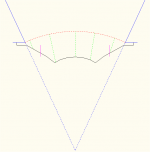
The concept I've drawn here is imperfect, (but so is the HOM performance of certain horns and therefore IMO the concept of the perfect driving wavefront shape for them).. so with a bandwidth based margin of error allowed for, a rule of thumb might be derived eg. the deviation between the longest and shortest distances to the desired wavefront, being essentially the distance from the edge of the dustcap, and how this relates to a wavelength.
Additionally, the magenta tick marks on the cone show the halfway radius where the cone area inside and outside them, looking from the front, are equal. This is to imply the relative contribution strength of the regions.
One of which comes down to cone geometry, which incidentally may give a more shallow cone with the 1:1 compression ratio.if you want extended bandwidth either you need a woofer close to your throat size, or use a phase plug with a larger woofer. The problem is there are very few smaller diameter woofers that can actually drive a horn without a compression throat (i.e. throat smaller than cone diameter). The M5N12 has the guts to do it. The flux gap in the M5N12 is 1.65T.
The concept I've drawn here is imperfect, (but so is the HOM performance of certain horns and therefore IMO the concept of the perfect driving wavefront shape for them).. so with a bandwidth based margin of error allowed for, a rule of thumb might be derived eg. the deviation between the longest and shortest distances to the desired wavefront, being essentially the distance from the edge of the dustcap, and how this relates to a wavelength.
Additionally, the magenta tick marks on the cone show the halfway radius where the cone area inside and outside them, looking from the front, are equal. This is to imply the relative contribution strength of the regions.
Attachments
You can do better.
Here is why:
WHG
P-Audio Faital
SN8-250N M5N12
BL 17.5 Tm 11.3 Tm
RE 5.7 Ohms 7.2 Ohms
MMS 0.02056 kg 0.0084 kg
Fhs 414 Hz 336 Hz
Sens 98 dB 99 dB
Xmax 4 mm 2.75 mm
Sd 227 cm² 94.3 cm²
Vd 90.8 cm³ 25.9 cm³
USD $160 $120
Hello whgeiger.
>snip<
The experiences Pooh and JLH have had with Faital M5N12 in a horn suggest good results can be obtained. They used axisymmetrical horns, though, so it's not a copy-n-paste project, but more like proof it can be done.
I believe I have chosen an accetable driver and now need to learn how to build a good performing horn to go with it. Going for a different driver will not be in the cards for a while.
>snip<
Here is why:
WHG
P-Audio Faital
SN8-250N M5N12
BL 17.5 Tm 11.3 Tm
RE 5.7 Ohms 7.2 Ohms
MMS 0.02056 kg 0.0084 kg
Fhs 414 Hz 336 Hz
Sens 98 dB 99 dB
Xmax 4 mm 2.75 mm
Sd 227 cm² 94.3 cm²
Vd 90.8 cm³ 25.9 cm³
USD $160 $120
thats insane.BMS 4599ND
what kind of waveguide you would put this?
counting my money
Nonsense!
Answer: I would put the BMS 4599ND compression driver in a very specific kind of waveguide, called an acoustic horn.
Insanity is reserved for those that would put this unit elsewhere, except for testing in a PWT, which incidentally is a waveguide as well.
Rhetorical Question: Why is it that arrogance and stupidity are such good friends, particularly on this website?
WHG
I have noticed the traffic on most of these bulletin board type of sites is way, way down. At one time, this DIY was the "place to be" for consideration of others and the sharing of knowledge. I think the hey-day was 2006 + - a few years here and there. It is also very alarming what I see of the world's society in general. Never before has right been declared so wrong and wrong declared so right.
- Home
- Loudspeakers
- Multi-Way
- Midrange horn design, cone-driven - 201