These are curves of horns 50cm wide 25 cm high with the upper having a phase plug and the lower does not. These measurements were made a very long time ago. I will come back with pictures of the horns soon.


Have you measured the response of said driver on a large flat baffle, outdoors ?
(I ask, because this way you can have a base-line performance reference)
I haven't. Was taking the factory curves as good. I can probably do that next weekend.
How large a baffle would be good enough?
Driver pointing horizontally, such that the floor bounce is still there despite the grass cover?
3) The horn design trade remains, LF loading verses HF pattern control.
For the former, use a Salmon horn with a low [T] value, for the latter use an OS horn with a effective coverage angle. To tweak frequency response at the upper end, use a phase plug.
Can you point me to an OS horn with 4" throat, 80x30 coverage or thereabouts? Preferably DIY although retail would also work.
I haven't. Was taking the factory curves as good. I can probably do that next weekend.
How large a baffle would be good enough?
Driver pointing horizontally, such that the floor bounce is still there despite the grass cover?
Have you considered [that if] your tractrix horn would have worked out okay, to actually add a baffle plate to the horn mouth ? If so, testing a similar dimension would be prudent. The wavelength of 400Hz is somewhere around
34 inches. Obviously, half that is 17, and one quarter is 8.5
A truncated baffle plate would be cool, with the top dimension to equal your Beyma TPL, and the bottom width to match your mid bass. c/c considerations might prohibit that idea, though. Having said that, triangle shaped baffles do image quite well.
(I would try the outdoors measurement in both vertical and horizontal positions, to see indeed if there is a "grass bounce" )
Might I suggest going back to the "Edgar mid-range horn" article and revisit what he speaks of in terms of using a gap mount at the throat mount. Also, I'm pretty sure he writes about how the larger throats actually sounded better than the (predicted) horn throat size. Bruce's horns were no where near as long (deep) as your 3rd trial.
Here's some info about the old IEC standard baffle (old-school) and it also contains some vital information concerning diffraction:
http://www.diy-audio.narod.ru/litr/Measuring_the_true_acoustical_response_of_loudspeakers.pdf
Lewinski,
Sorry I've been really busy doing some design work for a client. The horns in that picture were designed for use in small to mid sized rooms. They had very wide dispersion about 90 degrees across the entire bandwidth from 600hz up to 1.6Khz. What is not obvious is that the horn has a very small compression chamber before the throat expands and created a 25% loading of the cone area not including the surround. The expansion ratio was a hyperbolic expansion with if I remember correctly a T of 0.6. I have some raw ones that I could measure the exact dimensions but haven't gotten to that. The horns sounded good but at the time I was using a pro-audio Audax PR17 paper cone driver which I wouldn't use today. There was a correction circuit in the passive network to flatten the response but don't ask me what that was anymore. As for what that finish is on those enclosures that was a two part polyurethane automotive paint over a molded polyurethane enclosure. The wood is Coco Bollo and was a pain to work with. Both horns had the same dispersion angle and that helped to make the combination work so well. I really don't think you need a large horn in a normal room, we are not doing PA here. The efficiency I don't remember but there was plenty of horn gain. The problem always came down to having to pad the horns to match the low frequency drivers which weren't horn loaded so efficiency was never an issue except how to get rid of gain! Today I would use an active network or more realistically a dsp network and then things get much better and easier at the same time. There was not any problem with bandwidth but there was a slope function in the network to get the top frequency output to match the lower frequency output, otherwise the response was smooth but dropping with increasing frequency.
Sorry I've been really busy doing some design work for a client. The horns in that picture were designed for use in small to mid sized rooms. They had very wide dispersion about 90 degrees across the entire bandwidth from 600hz up to 1.6Khz. What is not obvious is that the horn has a very small compression chamber before the throat expands and created a 25% loading of the cone area not including the surround. The expansion ratio was a hyperbolic expansion with if I remember correctly a T of 0.6. I have some raw ones that I could measure the exact dimensions but haven't gotten to that. The horns sounded good but at the time I was using a pro-audio Audax PR17 paper cone driver which I wouldn't use today. There was a correction circuit in the passive network to flatten the response but don't ask me what that was anymore. As for what that finish is on those enclosures that was a two part polyurethane automotive paint over a molded polyurethane enclosure. The wood is Coco Bollo and was a pain to work with. Both horns had the same dispersion angle and that helped to make the combination work so well. I really don't think you need a large horn in a normal room, we are not doing PA here. The efficiency I don't remember but there was plenty of horn gain. The problem always came down to having to pad the horns to match the low frequency drivers which weren't horn loaded so efficiency was never an issue except how to get rid of gain! Today I would use an active network or more realistically a dsp network and then things get much better and easier at the same time. There was not any problem with bandwidth but there was a slope function in the network to get the top frequency output to match the lower frequency output, otherwise the response was smooth but dropping with increasing frequency.
One other note Lewinski,
To make a OB horn is about as simple as it gets. Basically it is a conic horn with a section to join the throat to the conic section. A simple way to do that is to just make the initial opening tangent to the exit angle of the driver and make it tangent to the conic section you decide you want. As Earl Geddes does he adds a large roundover at the end of the conic section to cover the terrible diffraction you would get from a conic section that just ends. Nothing really hard about making that type of horn flare.
To make a OB horn is about as simple as it gets. Basically it is a conic horn with a section to join the throat to the conic section. A simple way to do that is to just make the initial opening tangent to the exit angle of the driver and make it tangent to the conic section you decide you want. As Earl Geddes does he adds a large roundover at the end of the conic section to cover the terrible diffraction you would get from a conic section that just ends. Nothing really hard about making that type of horn flare.
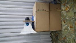
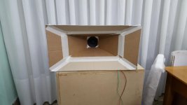
4th prototype: dual expansion conical
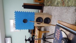
I used bwaslo's spreadsheet to come up with a conical dual expansion horn. No, it's not a Phillips horn...it's a horn made of the cardboard of a Phillips appliance 🙂
Since the tractrix prototypes didn't really load the bottom end as expected and since conical horns are known for their directivity properties, I tried this quick and easy.
What do you think?
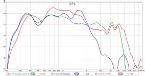
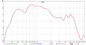
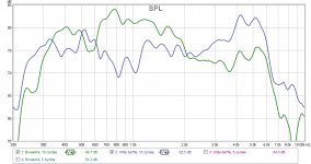
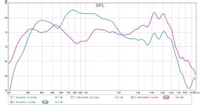
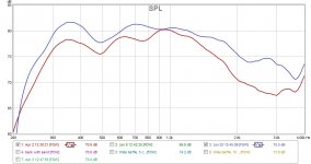
The first SPL chart shows this prototype in red, the 2nd proto with closed back (green), and the 2nd proto with closed back and dustcap on (blue). Second chart is this horn only, taken with FDW=5 cycles.
Seems the horn would be usable with 2kHz steep xo (active), right? And I wouldn't loose much on the low end, maybe xo at 400Hz. I think I should close the back and see how that affects the dip at 550-600Hz.
Next I would build an MDF version.
Feedback more than welcome! In fact, desired 😀
I used bwaslo's spreadsheet to come up with a conical dual expansion horn. No, it's not a Phillips horn...it's a horn made of the cardboard of a Phillips appliance 🙂
Since the tractrix prototypes didn't really load the bottom end as expected and since conical horns are known for their directivity properties, I tried this quick and easy.
What do you think?
The first SPL chart shows this prototype in red, the 2nd proto with closed back (green), and the 2nd proto with closed back and dustcap on (blue). Second chart is this horn only, taken with FDW=5 cycles.
Seems the horn would be usable with 2kHz steep xo (active), right? And I wouldn't loose much on the low end, maybe xo at 400Hz. I think I should close the back and see how that affects the dip at 550-600Hz.
Next I would build an MDF version.
Feedback more than welcome! In fact, desired 😀
Attachments
Scott,
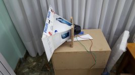
You are right, I had forgotten to do that. Did it today, quick and dirty, but I believe it's telling enough.
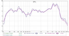
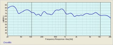
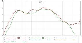
Attaching: manufacturer's response, my driver on the wide baffle at FDW=5 and 10 cycles, wide baffle vs Bwaslo's horn at 5 and 10 cycles FDW.
The dip doesn't appear to be there. Seems to be a horn artifact, doesn't it?
You are right, I had forgotten to do that. Did it today, quick and dirty, but I believe it's telling enough.
Attaching: manufacturer's response, my driver on the wide baffle at FDW=5 and 10 cycles, wide baffle vs Bwaslo's horn at 5 and 10 cycles FDW.
The dip doesn't appear to be there. Seems to be a horn artifact, doesn't it?
Attachments
Standing Wave Modes
Suspect several are combining to give such a broad response notch. These arise due to Mouth Reflectance, and Transvers Modes occurring in horn body, back and front chambers. Methods to mitigate these are well known.
Horn Mouth generating intense back waves, increase mouth size and round-over any diffraction edges.
Intense Transverse Waves
1) in horn body, nix diffraction slots and parallel sides
2) in back box , diversify the modes, use a three sided pyramid or similar
3) in front chamber, set phase-plug annuli a mode nodes al la Bob Smith.
Regards,
WHG
Thanks for the input.
I will build an MDF prototype and experiment with the round overs at the mouth. I guess the midbass section front panel at the bottom is acting as such. Will experiment on the sides. The top is most challenging given the need to keep the TPL-150H as close as possible to minimize c-to-c concerns.
No parallel sides in the horn body as it is a rectangular conical and 4 walls are angled. No diffraction slots.
The measured horn above does not have any rear chamber, so I guess this is not another issue adding to this mix. I do have a triangular section back chamber I can experiment with, though.
For the time being I won't introduce a phase plug.
Regards
Scott,
You are right, I had forgotten to do that. Did it today, quick and dirty, but I believe it's telling enough.
Attaching: manufacturer's response, my driver on the wide baffle at FDW=5 and 10 cycles, wide baffle vs Bwaslo's horn at 5 and 10 cycles FDW.
The dip doesn't appear to be there. Seems to be a horn artifact, doesn't it?
I'm sorry, I guess I am just too much "old school" to follow these. Is it possible for you to post JUST the curve of the raw driver ? Also, I don't know the terms
5 and 10 cycles FDW (????)
I'm sorry, I guess I am just too much "old school" to follow these. Is it possible for you to post JUST the curve of the raw driver ? Also, I don't know the terms
5 and 10 cycles FDW (????)
Scott,
On post #250, it's the second graph (the one with a blue and a purple line, with the legend showing "wide baffle, 10 cycles" and "wide baffle 5 cycles").
FDW means frequency dependant windowing. It's a parameter you set in REW (the measurement software), so at lower frequencies the "window" in which the measuring mic is "open" is longer than at higher frequencies. Longer windows allow more reflections to be recorded as measurement, which is especially misleading at higher frequencies. So FDW is a means to reduce this effect. By the same token, reducing the window also reduces the "definition", so it's a balancing act. Hence I measure both.
Update: conical double expansion
I've been having very little time to spend on the horns, but got around to assembling a conical dual expansion per bwaslo's spreadsheet and tried with two different openings in the mounting flange.
The horn is 60cm wide x 30cm high x 25cm long. The smallest part of the horn is 9 x 9cm, while flange 1 has a 7.5cm round opening and flange 2 has a 9cm square opening. The driver is a 5" (12.5cm).
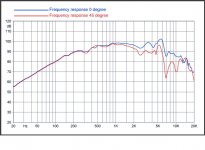
First graph shows measurements for both, open back driver, FDW 5 cycles. Red line is large throat 9x9, green is smaller 7.5cm diameter. The larger reaches further on both ends. In fact this horn seems to go deeper than I need so maybe I can make it a bit smaller for improved WAF.
BTW, how do I insert an image inline here? 😱
Second graph is the same above 9x9 opening vs. my 2nd prototype (Tractrix Edgar-style 50cm wide x 35 tall x 31 long). Unfortunately the measurements weren't made at the same SPL level, but it seems the conical dual expansion has a less severe dip around 480Hz and reaches higher. The tractrix has a larger throat.
I'm thinking of sticking with the conical dual expansion, but maybe 5cm narrower and with a larger throat, maybe 10x10.
Opinions?
I've been having very little time to spend on the horns, but got around to assembling a conical dual expansion per bwaslo's spreadsheet and tried with two different openings in the mounting flange.
The horn is 60cm wide x 30cm high x 25cm long. The smallest part of the horn is 9 x 9cm, while flange 1 has a 7.5cm round opening and flange 2 has a 9cm square opening. The driver is a 5" (12.5cm).
First graph shows measurements for both, open back driver, FDW 5 cycles. Red line is large throat 9x9, green is smaller 7.5cm diameter. The larger reaches further on both ends. In fact this horn seems to go deeper than I need so maybe I can make it a bit smaller for improved WAF.
BTW, how do I insert an image inline here? 😱
Second graph is the same above 9x9 opening vs. my 2nd prototype (Tractrix Edgar-style 50cm wide x 35 tall x 31 long). Unfortunately the measurements weren't made at the same SPL level, but it seems the conical dual expansion has a less severe dip around 480Hz and reaches higher. The tractrix has a larger throat.
I'm thinking of sticking with the conical dual expansion, but maybe 5cm narrower and with a larger throat, maybe 10x10.
Opinions?
Attachments
Potential Not Realized Yet!
I see a one-decade, speech-range bandwidth still 'on the table'. A properly designed phase plug, back box and a OS horn neck and body with mouth round-over will take you there. A compression ratio of say 4:1 would be a good target for efficiency. WHG
I see a one-decade, speech-range bandwidth still 'on the table'. A properly designed phase plug, back box and a OS horn neck and body with mouth round-over will take you there. A compression ratio of say 4:1 would be a good target for efficiency. WHG
I see a one-decade, speech-range bandwidth still 'on the table'. A properly designed phase plug, back box and a OS horn neck and body with mouth round-over will take you there. A compression ratio of say 4:1 would be a good target for efficiency. WHG
Indeed, I forgot to mention a phase plug is in the plans too. I'll take the 4:1 as a target and go from there.
Note I'm not needing a one-decade, but rather less than three octaves: 400 to 2200Hz would be outstanding.
I'm intrigued by the oblate spheroid neck. My understanding is an OS is a 3D object such as the Earth. So by OS horn neck we are referring to the cross section of the neck at different points...so elliptical cross sections of the neck? An ellipse with such a curvature ressembling a cross section of the Earth along a meridian?
Needless to say building this would be much more difficult than a dual conical, but oh well 😱
More Notes
1) Recommend good horn response be maintained in the one octave overlap regions at both ends of the pass-band. Some relief from this requirement can be gained by using sharper filter slopes in crossovers, but leave some margin here for tweaking later during system integration.
2) OS is the assumed wave front profile you get when horn boundaries are defined by hyperbolas.
Oblate Spheroidal Coordinates -- from Wolfram MathWorld
In the high-pressure region of the neck you want a decline in curvature as the wave moves away from the driver until the mouth is approached then curvature should then increase to form the horn mouth.
Once the general geometry has been established, a spline works well to smooth out the discontinuities of an approximate design.
3) Here is a good starting point:
http://www.diyaudio.com/forums/multi-way/103872-geddes-waveguides-284.html#post1851334
Beware it gets very contentious in this thread. Note the negative slope in the throat that assumes a concave wave front is entering the horn from the driver.
4) As you point out transformation from round to elliptical introduces additional complexity to the construction problem. Geddes is still using round section horns in his products, and claims the extra effort to make them otherwise does not deliver sufficient gains in pattern control to make it worthwhile.
5) Ideally what ever curve is used for the horn profile it should not contain (significant) discontinuities in its second derivative. The outbound wave, depending on frequency 'sees' these as diffraction edges that trigger HOMs and back-wave generation.
6) The horn design problem requires balancing the provision of adequate driver loading, while maintaining constant directivity, minimizing horn reflectance, and voicing the driver baffle system for uniform frequency response in the passband. As you will find, this is at best a 'greasy balloon squeeze'. For horns operating in the second decade all these factors are critical. Above and below this domain, some are more important than others.
Regards,
WHG
P.S. An Additional Reference:
http://www.diyaudio.com/forums/multi-way/103872-geddes-waveguides-766.html#post4986483
Indeed, I forgot to mention a phase plug is in the plans too. I'll take the 4:1 as a target and go from there.
Note I'm not needing a one-decade, but rather less than three octaves: 400 to 2200Hz would be outstanding.
I'm intrigued by the oblate spheroid neck. My understanding is an OS is a 3D object such as the Earth. So by OS horn neck we are referring to the cross section of the neck at different points...so elliptical cross sections of the neck? An ellipse with such a curvature ressembling a cross section of the Earth along a meridian?
Needless to say building this would be much more difficult than a dual conical, but oh well 😱
1) Recommend good horn response be maintained in the one octave overlap regions at both ends of the pass-band. Some relief from this requirement can be gained by using sharper filter slopes in crossovers, but leave some margin here for tweaking later during system integration.
2) OS is the assumed wave front profile you get when horn boundaries are defined by hyperbolas.
Oblate Spheroidal Coordinates -- from Wolfram MathWorld
In the high-pressure region of the neck you want a decline in curvature as the wave moves away from the driver until the mouth is approached then curvature should then increase to form the horn mouth.
Once the general geometry has been established, a spline works well to smooth out the discontinuities of an approximate design.
3) Here is a good starting point:
http://www.diyaudio.com/forums/multi-way/103872-geddes-waveguides-284.html#post1851334
Beware it gets very contentious in this thread. Note the negative slope in the throat that assumes a concave wave front is entering the horn from the driver.
4) As you point out transformation from round to elliptical introduces additional complexity to the construction problem. Geddes is still using round section horns in his products, and claims the extra effort to make them otherwise does not deliver sufficient gains in pattern control to make it worthwhile.
5) Ideally what ever curve is used for the horn profile it should not contain (significant) discontinuities in its second derivative. The outbound wave, depending on frequency 'sees' these as diffraction edges that trigger HOMs and back-wave generation.
6) The horn design problem requires balancing the provision of adequate driver loading, while maintaining constant directivity, minimizing horn reflectance, and voicing the driver baffle system for uniform frequency response in the passband. As you will find, this is at best a 'greasy balloon squeeze'. For horns operating in the second decade all these factors are critical. Above and below this domain, some are more important than others.
Regards,
WHG
P.S. An Additional Reference:
http://www.diyaudio.com/forums/multi-way/103872-geddes-waveguides-766.html#post4986483
Last edited:
Thanks for the link to the Geddes waveguides thread. Very interesting, and long. Over 500 pages...I've gone through the first 17, and some conclusions/impressions so far:
His waveguides are intended to be used from 900Hz and above. I'm guessing at higher frequencies the smaller imperfections have more of an impact than at the frequencies I'm looking at.
Everybody's talking about axis symmetrical waveguides. Easier to build and design.
Geddes uses 15" waveguides, too small for my application anyways.
Interesting idea of foam phase plugs to absorb HOMs.
Unfortunately the links aren't working from the posts from 2007 pointing to the spreadsheets people assembled. I'll play around with the equation posted on the initial pages and see if I come up with any ideas.
- Home
- Loudspeakers
- Multi-Way
- Midrange horn design, cone-driven - 201