covering the fundamental intelligence range
And then the question becomes, "What does it sound like ?"
I have discovered that the very best sounding systems do not have a crossover occurring in the Bells Labs voice intelligibility range.
If memory serves, isn't that 300-3k Hz ?
And then the question becomes, "What does it sound like ?"
I have discovered that the very best sounding systems do not have a crossover occurring in the Bells Labs voice intelligibility range.
If memory serves, isn't that 300-3k Hz ?
Scott,
I would have to say those old rules were specifically created when we were working with passive networks and even then there has never been consensus making those hard and fast rules. I've done plenty of systems that crossed at 600hz and then again at 1.6Khz. Depends on how adept you are at network design and what devices you are using together. Not saying that those rules don't make things simpler but they aren't set in stone rules. Dsp changes the game in many ways, beyond what you could even do with active networks that were similar to passive topologies.
I would have to say those old rules were specifically created when we were working with passive networks and even then there has never been consensus making those hard and fast rules. I've done plenty of systems that crossed at 600hz and then again at 1.6Khz. Depends on how adept you are at network design and what devices you are using together. Not saying that those rules don't make things simpler but they aren't set in stone rules. Dsp changes the game in many ways, beyond what you could even do with active networks that were similar to passive topologies.
I am just sharing my experiences here, sir. There are many paths to nirvana.
I spent some time and re-read every single post in this thread. Man Oh man, it just makes me want to build a cone driven mid range horn using my own advice. I am thinking post #2 is the single most informative ( which was not mine, but obviously written by someone in the know. )
I spent some time and re-read every single post in this thread. Man Oh man, it just makes me want to build a cone driven mid range horn using my own advice. I am thinking post #2 is the single most informative ( which was not mine, but obviously written by someone in the know. )
Sounds good. Impedance induced response variations might need attention. Although I would use passive zobel compensation on the driver, in my experience this is a fiddly situation calling for individual tuning per channel if necessary, and good sealing of the rear chambers aiming for stability. A solid state amp is a good tool during the build until this is nailed down.I'm also hoping I can drive the midrange horn with a dedicated 45 SET using up to 1W,
The low end will mostly follow one path along the horn, ie even throughout the reflection it will mostly backtrack along the same path. This makes it a potential candidate for EQ.You mean 15/30/45 degrees horizontally, right?
Scott,
The equation for the rear enclosure in post #2 is from Paul Klipsch. I was pointing to that same equation myself but didn't remember it exactly so didn't put it up so someone wouldn't go it wrong. That creates a fairly small rear enclosure even when I did some double 18" bass horns the rear enclosure was very small. Like that poster I also like the hyperbolic expansion rates and usually used a factor of 0.6 for the "T" value.
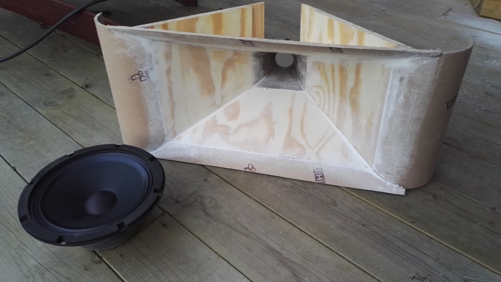
ps My icon is of some horn loaded enclosure I did in the early 90's. The bottom horn you see is a mid horn with a 6 1/2" driver that was push down to 400hz. There is a down firing 8" driver in that particular model for the bass, it was a reflex tuning for that driver.
The equation for the rear enclosure in post #2 is from Paul Klipsch. I was pointing to that same equation myself but didn't remember it exactly so didn't put it up so someone wouldn't go it wrong. That creates a fairly small rear enclosure even when I did some double 18" bass horns the rear enclosure was very small. Like that poster I also like the hyperbolic expansion rates and usually used a factor of 0.6 for the "T" value.
ps My icon is of some horn loaded enclosure I did in the early 90's. The bottom horn you see is a mid horn with a 6 1/2" driver that was push down to 400hz. There is a down firing 8" driver in that particular model for the bass, it was a reflex tuning for that driver.
Last edited:
Lewinski, did you at any point try the horn with a secondary flare (like often found on Synergy horns)?
I bet the project from Weltersys could also show what I mean, he made a removable second flare.
Sort of like this Synergy:

(but you could also use a round extension, like suggested earlier. An even clearer example would be onni's Synergy build:
But instead of using it on the sides like onni did, use it to extend the top and bottom. A picture should help to get the idea.
You can use simple materials to try it out, like Kindhornman's suggestion of foam rolls.
I bet the project from Weltersys could also show what I mean, he made a removable second flare.
Sort of like this Synergy:
(but you could also use a round extension, like suggested earlier. An even clearer example would be onni's Synergy build:
But instead of using it on the sides like onni did, use it to extend the top and bottom. A picture should help to get the idea.
You can use simple materials to try it out, like Kindhornman's suggestion of foam rolls.
Last edited:
Yes measure horizontally. Usually the listening axis vertically isn't that wide just sitting or perhaps standing for short periods. As far as using those 10" driver I would think any decent 10" should go up to 800hz with no breakup modes, no reason to limit them to 400hz. A good 15" can easily go to 600hz with no breakups. You should be able to go as high as 1200hz no problem with the 10" cones. I don't think the mouth size if the problem you are seeing with the 480hz dip, you would see the lower frequencies also dropping off if that was the case. Rectangular mouthed horns with abrupt termination as you have will have many issues with internal modes interacting across the opening. An elliptical mouth opening of the same size and aspect ratio would look very different in response on and off axis due to internal reflective modes.
ps. not being a SE tube guy I would still think any competently designed tube amp like that should be capable of 5-7 watts of output.
My midbasses are Beyma 10G40, that can easily go to 800Hz without breakup, low distortion, and linear impendance. I was trying to keep them lower, though. Maybe I could use them from 80 to 600Hz and keep them operating within 3 octaves. And maybe reduce the size of the horn by using fc of 300Hz (instead of 200Hz today). Even shift the aspect ration from 1.5:1 towards 1:1.
I'll make a mental note about all this while I continue to explore what can be achieved with the current prototype. I'm getting very valuable input.
BTW, 45-type tubes deliver 2W. SETs perform their best if used below 25% of their rated power, so I'm using 50% as the max. 2A3 tubes deliver 4W, and 300B deliver 8W. I'm hoping for 45s though.
Sounds good. Impedance induced response variations might need attention. Although I would use passive zobel compensation on the driver, in my experience this is a fiddly situation calling for individual tuning per channel if necessary, and good sealing of the rear chambers aiming for stability. A solid state amp is a good tool during the build until this is nailed down.
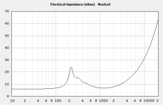
Considering how the impedance of this driver varies (8 to 11 ohm) within the intended operating range (400-2500Hz), I thought I should work without a Zobel
http://www.faitalpro.com/products/files/M5N8-80/12/M5N8-80_curves_12.pdf
Please confirm the convenience of using a Zobel here, since the amp will only drive this one driver.
My next step is to make the rear chamber really small and properly sealed.
Lewinski, did you at any point try the horn with a secondary flare (like often found on Synergy horns)?
Thanks for the suggestions!
I didn't try any of these, but explored Weltersys' design some and concluded it was just too large for my room.
I will try with the round extensions up and down. The upper piece would become a challenge considering the tweeter above and center-to-center spacing increasing, but let's first see if the roundings fix the issue. What radius would you suggest for the roundovers? 8cm radius OK?
Lewinwki,
The last tube gear I used for a show were Cary amps with the 300B tubes. Before that I had some old McIntosh amps that had 6BG6 power tubes I think with 12ax7 and 12au tubes if I can remember more than 20 years back.
The last tube gear I used for a show were Cary amps with the 300B tubes. Before that I had some old McIntosh amps that had 6BG6 power tubes I think with 12ax7 and 12au tubes if I can remember more than 20 years back.
I'm referring to the low end (not the series RC often associated with Zobel). I would expect the impedance here to be an issue affecting the response in a lower midrange tractrix horn that is exposed to some source impedance. Ie: a passive crossover or a SET amp.Please confirm the convenience of using a Zobel here, since the amp will only drive this one driver.
My next step is to make the rear chamber really small and properly sealed.
Attachments
Thanks for the suggestions!
I didn't try any of these, but explored Weltersys' design some and concluded it was just too large for my room.
I will try with the round extensions up and down. The upper piece would become a challenge considering the tweeter above and center-to-center spacing increasing, but let's first see if the roundings fix the issue. What radius would you suggest for the roundovers? 8cm radius OK?
The 8 cm radius should show you if there's a difference. What would stop you from mounting the tweeter inside that round-over space with a bit of work. 🙂 Do the time align in DSP.
segway to another line of thinking
'45s are best served up driving a VERY efficient compression driver. Running your mid-bass units up to 800Hz would allow you that flexibility because you should more easily be able to find a driver/horn combo that will be an acceptable size for your project, covering from 800-5kHz. The caveat here is that the mid-bass section would be the predominant influence on the sound quality of your system. Realizing this proposal is quite the departure, I suggest visiting the thought of a "wave-guide" for your mid-range cone driver, as opposed to a horn.
My midbasses are Beyma 10G40, that can easily go to 800Hz without breakup, low distortion, and linear impendance. I was trying to keep them lower, though. Maybe I could use them from 80 to 600Hz and keep them operating within 3 octaves. And maybe reduce the size of the horn by using fc of 300Hz (instead of 200Hz today). Even shift the aspect ration from 1.5:1 towards 1:1.
I'll make a mental note about all this while I continue to explore what can be achieved with the current prototype. I'm getting very valuable input.
BTW, 45-type tubes deliver 2W. SETs perform their best if used below 25% of their rated power, so I'm using 50% as the max. 2A3 tubes deliver 4W, and 300B deliver 8W. I'm hoping for 45s though.
'45s are best served up driving a VERY efficient compression driver. Running your mid-bass units up to 800Hz would allow you that flexibility because you should more easily be able to find a driver/horn combo that will be an acceptable size for your project, covering from 800-5kHz. The caveat here is that the mid-bass section would be the predominant influence on the sound quality of your system. Realizing this proposal is quite the departure, I suggest visiting the thought of a "wave-guide" for your mid-range cone driver, as opposed to a horn.
(Going OT with Scott)
I like this train of thought, as long as sensitivity is over 100 I think the 45s should do well. I'm using conservatively run 6V6s (SET) above 300Hz with good levels.
800Hz does set up a bit of a barrier. Size is one (corners are interesting 😉), and waveguide style horns begin to falter in efficiency below this point, but if a person can come to a compromise of size and horn contour they can edge toward the upper bass with similar efficiency (so as not to need to pad the tweeter). Not easy I know, but since one driver can be made to cover 800->, it seems a shame not to try.
Something to be arrived at I suppose 😕
The 8 cm radius should show you if there's a difference. What would stop you from mounting the tweeter inside that round-over space with a bit of work. 🙂 Do the time align in DSP.
Sure I can carve out some room for the tweeter inside the roundover, but wouldn't that affect the effect of the roundover? I guess that's another thing to try.
Yes, I will be time-aligning in DSP. FWIW, digital xo in Acourate, time-aligned, linearized, room-corrected.
'45s are best served up driving a VERY efficient compression driver. Running your mid-bass units up to 800Hz would allow you that flexibility because you should more easily be able to find a driver/horn combo that will be an acceptable size for your project, covering from 800-5kHz. The caveat here is that the mid-bass section would be the predominant influence on the sound quality of your system. Realizing this proposal is quite the departure, I suggest visiting the thought of a "wave-guide" for your mid-range cone driver, as opposed to a horn.
I'm afraid you are talking about a different project, and I'm not prepared to abandon this one yet. My TPL tweeters are not the best option if one wants to start using then at 5kHz. Neither is a cone-driven horn.
Midbasses are driven by Hypex class-D, 400W per channel, so plenty of power there. But the 10G40 weren't chosen for their capabilities above 400Hz, but rather their performance around 80Hz and up to 400Hz or so. 600 might be acceptable, but I doubt 800Hz would be.
(Going OT with Scott)
I like this train of thought, as long as sensitivity is over 100 I think the 45s should do well. I'm using conservatively run 6V6s (SET) above 300Hz with good levels.
800Hz does set up a bit of a barrier. Size is one (corners are interesting 😉), and waveguide style horns begin to falter in efficiency below this point, but if a person can come to a compromise of size and horn contour they can edge toward the upper bass with similar efficiency (so as not to need to pad the tweeter). Not easy I know, but since one driver can be made to cover 800->, it seems a shame not to try.
Something to be arrived at I suppose 😕
My understanding is 6V6 are rated for 5W. I also understand the midway point for power consumption is around 350Hz, so close enough to your 300Hz. And you are using rated 5W above 300Hz. Following my same assumption above, SETs are best under 50% of rated power, so 2.5W in your case above 300Hz.
My setup will have 1W (at 50% of rating) for the tweeter + 1W for the midrange which seems it's going to start somewhere in the 500-600Hz region. And each driver will be actively driven. Also plenty of power below that. So on paper my plan looks OK to me.
I have them running under 1W (which is right about where DHTs will be if/when I get around to their filament supplies).
I did some scoping and poking around a few years ago and decided I could use anything over 100mW (if I remember correctly) for above 800Hz so I figured it was a non issue. I don't know exactly but I've estimated they are 105dB sensitive (crossed) and so are the mids.
I did some scoping and poking around a few years ago and decided I could use anything over 100mW (if I remember correctly) for above 800Hz so I figured it was a non issue. I don't know exactly but I've estimated they are 105dB sensitive (crossed) and so are the mids.
Last edited:
I filled the back chamber with expandable foam (polyurethane) and properly sealed the chamber. Up until now the back chamber wasn't fully sealed as the back cover could be slid out. Now it's sealed and filled. Unfortunately I don't have the connectors yet to be able to measure the impedance peak, but measured frequency response again.
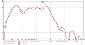
Graph #1 shows the horn with back chamber filled with sand (in ziplock) before sealing vs. sealed chamber and filled with polyurethane foam. There is some improvement. I might need to reduce the space further. These measurements were made without the foam "panels" shown in the picture.
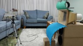
The picture displays a further experiment following what was suggested in the posts above.
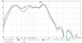
Graph #2 displays the measurement shown in #1 with polyurethane back chamber, plus a measurement with the bottom panel only (blue foam), plus a measurement with the bottom and top (green) foam. The blue panel definitely improved things. The top one also did, but marginally better than the bottom panel only.
What should I conclude/do, though? The bottom panel covering the midbasses aren't a realistic option I think. But do these results suggest the mouth should be made larger to xo at 400-450Hz.
Graph #1 shows the horn with back chamber filled with sand (in ziplock) before sealing vs. sealed chamber and filled with polyurethane foam. There is some improvement. I might need to reduce the space further. These measurements were made without the foam "panels" shown in the picture.
The picture displays a further experiment following what was suggested in the posts above.
Graph #2 displays the measurement shown in #1 with polyurethane back chamber, plus a measurement with the bottom panel only (blue foam), plus a measurement with the bottom and top (green) foam. The blue panel definitely improved things. The top one also did, but marginally better than the bottom panel only.
What should I conclude/do, though? The bottom panel covering the midbasses aren't a realistic option I think. But do these results suggest the mouth should be made larger to xo at 400-450Hz.
Attachments
Do you think there are two issues, one near 500 (rear chamber), and one at 550 (mouth)?
Some suggest sizing the rear chamber for reactance annulling. This can be fiddly to get right for the benefit of HD, if that is important, but it takes an impedance plot to tune well.. Personally I like to consider group delay as well, something for later maybe.
The rear chamber appears to be affecting the highs.
- Home
- Loudspeakers
- Multi-Way
- Midrange horn design, cone-driven - 201