I have two microwave transformers for 230v mains. they are gaped to support DC
could one be used as output transforemr for SE triode amp ?
230v secondary is maybe good for 16ohm speaker?
could one be used as output transforemr for SE triode amp ?
230v secondary is maybe good for 16ohm speaker?
They are not gapped, they have a magnetic shunt, which is quite different, and probably problematic for 99% of amplifier topologies
Since the devices are from consumer electronics (kitchen appliances) I'd expect that their laminations are selected for cost (M22 or worse) as opposed to M6/M4 steel. The core losses and distortion at >1kHz are probably not great.
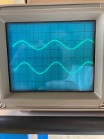
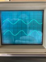
MOT cores are slow. They start to distort sine waves from about 1kHz and upwards.
Below are traces from an Arch Nemesis, a MOSFET driving an 8:1 OPT made from MOT cores. Top trace input, bottom trace is output across the secondary, feeding an 8R load.
Below are traces from an Arch Nemesis, a MOSFET driving an 8:1 OPT made from MOT cores. Top trace input, bottom trace is output across the secondary, feeding an 8R load.
Attachments

yes I know that MOT are great un MoFo and LuFo buffers but since mines are 230v the dcr of primary is quite highTry LuFo, or SusyLu. If you have power jfet lu1014. Plenty available.
then comed the idea of triode SE with some gain
Even if the core would work, you'll have to:
-Remove the magnetic shunt
-Create a new bobbin and rewind, using interleaving.
-Cut the welds to take off the I laminations.
-Remove the magnetic shunt
-Create a new bobbin and rewind, using interleaving.
-Cut the welds to take off the I laminations.
I can't see a concern with using them for SE. Afaik, the secondary would be your SE primary, so perhaps do a turns ratio test to see if they are close to 10:1, which may then allow a 1k6 ohm primary impedance for 16 ohm speaker. That will then give you some idea of what output stage valves may be appropriate.
Afaik, a microwave oven uses a doubler rectifier, so the core isn't designed for DC operation per se, but likely has an incremental inductance that doesn't change much up until a certain application level of dc and ac. You could measure that using a relatively simple test jig such as in https://dalmura.com.au/static/Choke measurement.pdf. Measuring the primary winding inductance (ie. the HV winding) is important as it will then give you some idea of what your low frequency response could be. An even simpler measurement is just to use say a 12Vac supply and an AC current meter (or resistor for current sense), and doing the calculation.
The core construction is for cheapness, with a weld along the butted laminations. That does provide a form of gap, somewhat similar to what many PP cores use (eg. alternating groups of lamination directions) as a way to allow dc unbalance in a PP output stage, but not a significant gap aiming for a certain inductance as used by chokes.
Does your core construction include visible shunt lamination sections (eg. see https://www.qsl.net/kh6grt/page4/xfmr/pictures/transorig.jpg )? It may be practical to knock them out, as a way of reducing leakage inductance.
I wouldn't take post #5's results as generic until some better measurement data is presented.
There is an interesting thread about using MW transformers as OPTs: https://www.diyaudio.com/community/...transformers-into-output-transformers.391040/
- Home
- Amplifiers
- Tubes / Valves
- microwave MOT as SE output transformer