😀
This new thread here is another update from my previous thread asking for help with designing a 4th order enclosure without known TS parameters
Now the parameters were here !!! i am lucky enough that i didnt rush to construct and build the trial and error version 😀
ok first things first the TS parameters for those out there keep trying to help me
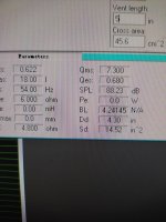
QTS = 0.622
QMS = 7.3
QES = 0.68
Vas = 18L
FS = 54Hz
Z = 4.8ohms
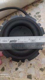
diameter 4.3inch
SD 14.57 inch
that is the best i could get and Vas i've averaged out after 3 times measurement.
Now another story
when i ran my simulation on WinISD ... it returns out results of suggesting very large enclosure size for this particular micro subwoofer especially it was only a 4.5 inch driver no doubt it has very low FS and fairly long excursion ... in my previous thread i did post a concern about the over excursion issue and therefore against the use of ported system and try something to control the excursion due to during listening test with my test box it slammed the back pole piece quite few times the cracking noise (50W driver powered by 300w amplifier)
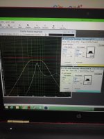
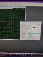
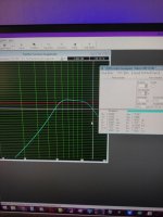
after simulation on WinISD was two graphs one showing the "RANDOM PROBBED TRIAL AND ERROR" 4th order bandpass design (light blue line) vs another one suggested by WinISD (yellow line) which was pretty large in box volume. I dont want to get it wrong again this time. And there was also a photo of the current garbage trial and error 4th order bandpass design ... what i've experienced peaking response around the midbass was accurately simulated by WinISD.
so the issue now the bigger volume suggested by the simulator is a good news or what? or might be something worse? i dont have much experience on 4th order bandpass system wish some experts here can help me out ... thanks
This new thread here is another update from my previous thread asking for help with designing a 4th order enclosure without known TS parameters
Now the parameters were here !!! i am lucky enough that i didnt rush to construct and build the trial and error version 😀
ok first things first the TS parameters for those out there keep trying to help me
QTS = 0.622
QMS = 7.3
QES = 0.68
Vas = 18L
FS = 54Hz
Z = 4.8ohms
diameter 4.3inch
SD 14.57 inch
that is the best i could get and Vas i've averaged out after 3 times measurement.
Now another story
when i ran my simulation on WinISD ... it returns out results of suggesting very large enclosure size for this particular micro subwoofer especially it was only a 4.5 inch driver no doubt it has very low FS and fairly long excursion ... in my previous thread i did post a concern about the over excursion issue and therefore against the use of ported system and try something to control the excursion due to during listening test with my test box it slammed the back pole piece quite few times the cracking noise (50W driver powered by 300w amplifier)
after simulation on WinISD was two graphs one showing the "RANDOM PROBBED TRIAL AND ERROR" 4th order bandpass design (light blue line) vs another one suggested by WinISD (yellow line) which was pretty large in box volume. I dont want to get it wrong again this time. And there was also a photo of the current garbage trial and error 4th order bandpass design ... what i've experienced peaking response around the midbass was accurately simulated by WinISD.
so the issue now the bigger volume suggested by the simulator is a good news or what? or might be something worse? i dont have much experience on 4th order bandpass system wish some experts here can help me out ... thanks
Attachments
Assuming you have to control excursion using the box (i.e. you don't have an adjustable highpass aka subsonic filter on your amp), I recommend 14L rear chamber, 12L front, 80hz tuning. It should take the full 30watts without problems, but it doesn't use the potential of the driver as well as a different design (which counted on highpass filtering) would.
Ya that is the concern over here mainly more over the excursion issue as now i found that this driver has such low fs i am trying to get something close to its Fs (40hz to 90hz) pass band. Excursion issue i think that it might be something to do with the high Qms value (lack of mechanical damping) this cone is very easy to be pushed downwards using fingers
Assuming you have to control excursion using the box (i.e. you don't have an adjustable highpass aka subsonic filter on your amp), I recommend 14L rear chamber, 12L front, 80hz tuning. It should take the full 30watts without problems, but it doesn't use the potential of the driver as well as a different design (which counted on highpass filtering) would.
ok as what you had suggested i am getting to pretty much close to the results you mentioned ... around 78Hz close enough to 80Hz ... while passband around 48hz to 120hz ...
but it would be nicer to extend the lower passband to around 40hz 😀
Attachments
Hmm, you list Sd = 14.57"^2 = 94 cm^2 = 9400 mm^2, but input 1452 mm^2 in WINisd, so which is correct?
Also don't see an Xmax, yet Chompy asserts it can handle 30 W, so what am I missing?
Also don't see an Xmax, yet Chompy asserts it can handle 30 W, so what am I missing?
oh no i did a mistake here ... actually it was in inches rather then in mm ... i did noticed that too ...
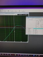
below another simulation with corrected data ... and the over excursion problem is still here ... the 13L sealed section simply not enough to prevent over excursion (passband 50Hz to 134hz) the upped passband was not too much a concern as i am using it with a subwoofer controller (Low pass filter) but it doesnt have a subsonic filter.
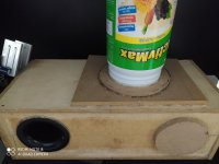
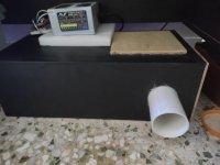
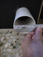
i've attached 2 graph from winisd with corrected data ... close snapshot of the parameters ... and there were 2 photos of a temporary test box of the 4th order bandpass enclosure salvaged from previous 4th order bandpass enclosure experiments. Sealed section 13L vented 12L with a basic 3inch pvc pipe as port extended outwards so it didnt affect the volume of the ported chamber. Over excursion and bottoming out still happens especially around 35hz to 40hz region ... uhh i thought that 4th order bandpass could control excursion problems pretty well?
below another simulation with corrected data ... and the over excursion problem is still here ... the 13L sealed section simply not enough to prevent over excursion (passband 50Hz to 134hz) the upped passband was not too much a concern as i am using it with a subwoofer controller (Low pass filter) but it doesnt have a subsonic filter.
i've attached 2 graph from winisd with corrected data ... close snapshot of the parameters ... and there were 2 photos of a temporary test box of the 4th order bandpass enclosure salvaged from previous 4th order bandpass enclosure experiments. Sealed section 13L vented 12L with a basic 3inch pvc pipe as port extended outwards so it didnt affect the volume of the ported chamber. Over excursion and bottoming out still happens especially around 35hz to 40hz region ... uhh i thought that 4th order bandpass could control excursion problems pretty well?
Attachments
-
 228798386_379414030365403_3989273143150400167_n.jpg60.4 KB · Views: 92
 -
 229540236_1684512568413545_2491479843241961281_n.jpg56.5 KB · Views: 91
 -
 222058396_975727396615390_4359404321831147547_n.jpg128.1 KB · Views: 92
 -
 223113070_359770755739545_4642666001988547756_n.jpg87.4 KB · Views: 100
 -
 221238963_540378647289412_7356658159140605013_n.jpg92.7 KB · Views: 102
With a Qts of 0.6 I think they require DSP to function best. Then the frequency response does not have to be flat any more and the cabinet can be designed as a compromise between primarily size and maximum output.
A 4th order bandpass box only controls excursion near the tuning frequency which is ~80 Hz. Expecting 35 Hz from a 4.5" woofer is realistic, though not at higher sound pressure levels than background music.
A 4th order bandpass box only controls excursion near the tuning frequency which is ~80 Hz. Expecting 35 Hz from a 4.5" woofer is realistic, though not at higher sound pressure levels than background music.
Last edited:
exactly what i am experiencing ... i dont have DSP but instead have a subwoofer low pass filter with modified shelving low end EQ ... when the shelving mode is turned on ... on certain bass tracks such as Bassotronics - Bass i love you = i heard even 35hz were reproduced and exiting from the port
but somewhat DSP or any bass boost approach is putting the driver in danger due to over excursion issue ... that is the point why i am against designed it in mind using a ported enclosure (my subwoofer controller doesnt have subsonic filter)
therefore i went into the approach of 4th order bandpass hoping that it will tackle the over excursion issue ... it did handle the over excursion issue better than ported but it still happening
Driver displacement increases 4x/octave, so small driver + low Xmax + high Fs = no low bass at any useful [peak] SPL without an incredibly large bass horn attached to it and even then it would only handle a fraction of a watt, though its base efficiency will of course be quite high.
For what it's worth, I figured OP didn't have xmax and xmech figures, nor would be able to get them, but their driver does appear solidly built, so ~10mm xmech and ~5mm xmax might be available (based on other small high excursion drivers like the dayton tcp115). It turns out that's way too high, but I didn't want to give OP a design that limited performance if it could indeed handle fairly high excursion cleanly. With that in mind, with 30w input the rear chamber appeared to need to be 14L (or smaller), to keep excursion to around 10mm. Then the front chamber size and tuning was adjusted for a flat response.
I will try again (smaller, higher tuning) since even that was too large.
Edit: maybe 4L rear, 5.5L front, 120hz?
If you want it to be loud all you are going to get is an 80-180hz 'boombox'-style bass unit like this. It still may be useful to you.
I will try again (smaller, higher tuning) since even that was too large.
Edit: maybe 4L rear, 5.5L front, 120hz?
If you want it to be loud all you are going to get is an 80-180hz 'boombox'-style bass unit like this. It still may be useful to you.
Last edited:
You can try to lower the Qts to 0.4-0.45 by fixing a 5-10mm layer of damping material directly across the basket openings. I used rubber bands to fix the material.
This will allow you to get smaller cab and it will also dampen the excursion.
Additionally you can put a couple of those magnets from HD on the back to increase the magnetic field which also lowers Qts
This will allow you to get smaller cab and it will also dampen the excursion.
Additionally you can put a couple of those magnets from HD on the back to increase the magnetic field which also lowers Qts
Last edited:
For what it's worth, I figured OP didn't have xmax and xmech figures, nor would be able to get them, but their driver does appear solidly built, so ~10mm xmech and ~5mm xmax might be available (based on other small high excursion drivers like the dayton tcp115). It turns out that's way too high, but I didn't want to give OP a design that limited performance if it could indeed handle fairly high excursion cleanly. With that in mind, with 30w input the rear chamber appeared to need to be 14L (or smaller), to keep excursion to around 10mm. Then the front chamber size and tuning was adjusted for a flat response.
I will try again (smaller, higher tuning) since even that was too large.
Edit: maybe 4L rear, 5.5L front, 120hz?
If you want it to be loud all you are going to get is an 80-180hz 'boombox'-style bass unit like this. It still may be useful to you.
Currently the mid bass and drum bass i am satisfied enough and of course in this range it does get loud enough ... But the lower end from 35hz till 48hz it was missing but it turns up when i applied the shelving EQ but in turns bring up the excursion issue ... Lately what i had in mind maybe i will do an isobaric approach ... Rear chamber will do around 8L and front 7.5L and see does it curb the excursion issue. I have 2 units of these drivers another one is still in breaking in
For what it's worth, I figured OP didn't have xmax and xmech figures, nor would be able to get them, but their driver does appear solidly built, so ~10mm xmech and ~5mm xmax might be available (based on other small high excursion drivers like the dayton tcp115). It turns out that's way too high, but I didn't want to give OP a design that limited performance if it could indeed handle fairly high excursion cleanly. With that in mind, with 30w input the rear chamber appeared to need to be 14L (or smaller), to keep excursion to around 10mm. Then the front chamber size and tuning was adjusted for a flat response.
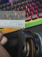
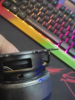
2 photos here ... one measured 5mm cone at resting position another one fully pressed inwards the surround roll is level flush = does it suggest one way xmax of 5mm? or this is xmech? this is another spare same unit ... the other one was inside the bandpass enclosure i guess it should be same the parameters
Attachments
To test Xmax, I'd get the driver in free air, and hit it with a 20Hz sine wave. Start with the volume low, and turn it up slowly.
At some point, you'll hear the driver going "thud" at each end of the cone travel - that's a very obvious indicator that it's struggling to move any further.
Reduce the level to just below the "thud", and estimate Xmax from there.
It's not scientific, but it does give an idea of the capabilities of the driver. In the simulations, you'll know that exceeding that excursion is likely to sound bad.
Chris
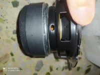
Seeing what the xmax of this driver is shouldn't be too difficult. In fact you're half of the way there with this picture
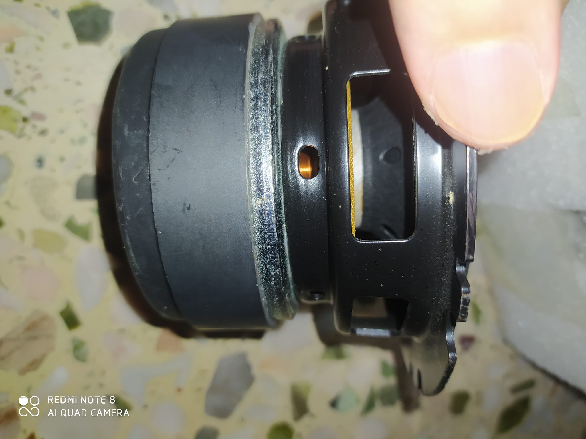
You can see the voice coil directly through the under spider venting hole. All you need to do is look through it and estimate how much coil length there is above the pole piece when the driver is at rest.
As far as I know, and this may have been mentioned before, this is the driver that is used in the original Apple Homepod. It uses a sealed box with plenty of EQ. I did read somewhere that the driver has 10mm of one way xmax but that seems a little too good to be true. Only way you'll know is to get looking through those vents.
Between where the coil apparently ends and the width of the magnet implies a mini 'monster' power handling.
Yeah it's clearly been designed to exploit the small, quiet, deep aspect of the Iron Law.
You can actually buy these on Aliexpress if you want and they aren't that expensive either.
You can actually buy these on Aliexpress if you want and they aren't that expensive either.
i bought these from china online store .... seems like they were selling as spare parts (really cheap around USD 4.25 = about MYR ringgit RM18 for one) which to me is a real bargain ... initially my first impression seems to be an interesting driver and i dont have the idea of the original application too 😀
- Home
- Loudspeakers
- Subwoofers
- Microsub redesign 4th order bandpass enclosure with know TS parameters