My comments on this is that the "typical" design is...
1) the input transformer is a 1:10 unit that is built inside a double sheathed can with wire leads common out a threaded tube that is also used to mount the transformer. This might say the intent is to mount the transformers on a bulkhead and keep is away from just about everything.
2) there is a 20 dB pad in the mic side of the transformers built wit resistors and a dpdt switch. Also the would be a polarity switch and a 48V phantom power supply all on the mic side of the transformer
3) There is a (say) 200K pot acros the transformer secondary and the wiper goes stright to the grid. I think layout matters a lot and I've seen designs that use a lot of sheet metal for compartmentalization
4) regulated DC heaters
5) fairly complex B+ supply
I think once the signal is out of the first tube you can worry less about noise. I might use a paralled triode for the first gain section
I've also seen balanced amps. These have one tube on each leg of the transformer secondary, it's basically two amps one for the in phase and one on the out of phase signal so there are no single ended sections in the signal path. This doubles the cost but "big deal" preamp tubes at $20 each, not much. Nothing compared the cost of a mic or an hour of an engineer's time.
Last edited:
Ian
At the moment im still behind on reading material.
I have both Morgan Jones
Allen Wright Preamp Cookbook
High-end Vlave amplifiers 2
Analogue Circutis (world class designs) R. Pease
I also have soft copies of Radio Designers Handbook etc.
Can you recommend any reading material for me? Something a bit more inclined towards microphone preamps
Cheers
Charlie
I would recommend study the design of low noise circuits. Valley and Wallman is a good start.
"Vacuum Tube Amplifiers" Valley and Wallman. MIT Radiation Lab Series
Also study microphones. There is a huge range of signal characteristics across different microphones, and a single type of input circuit is far from ideal for all of them. These have a lot of useful background.
"AIP Handbook of Condenser Microphones" Wong and Embleton. AIP Press
"Microphone Engineering Handbook" Michael Gayford. Focal Press
"The Microphone Book" John Eargle. Focal Press
A good studio mic preamp has different optimization from other types of preamp, but may have similar gain to a phono preamp. The circuits can be operated at relatively low impedance (1600 ohms input is one standard) and this can be exploited to reduce the input noise.
Gain needed will be from ~40 dB for condenser mics to 70 dB or more for low output dynamic mics. Fortunately, many low output mics are also very low impedance and will drive ~100 ohm input load from the preamp.
Also be careful about the output impedance. A lot of studio gear has low input impedance, less than the typical 10K ohm "Hi-Fi" minimum. Some gear is in the 5K range, and many vintage processors like the LA-2A, Fairchild 660, UA 176, etc. have actual 600 ohm inputs with transformers that like to be driven from a low impedance ~100 ohm or less source.
One of the big advantages of tube gain stages is voltage headroom. Some condenser tube mics can put out several volts signal when driven by loud sources and even the human voice on peaks. Combine this with say 45db of gain and a little creative signal squashing is hard to avoid. It's good to think about the maximum signal level the pre will pass (dynamic headroom) before clipping.
Transformers are your friend in mic pres. The low input impedance drives an input transformer just fine and the isolation is unbeatable. A step-down output transformer is nice also, particularly to achieve a reasonable power gain i.e. output drive capability from a tube stage. Or you can add a cathoe follower stage.
Gain control can be through an attenuator, but that will degrade the S/N ratio. Whether this is acceptable depends on the amount of gain needed and the input signal level vs. EIN i.e. the noise headroom.
Also the sound of a mic pre is very much dependent on the distortion spectrum produced, much like the power amps we usually discuss here. There can be SET mic pre circuits (UA1008), single ended pentode circuits (Telefunken V72, V76), balanced differential and push-pull (UA1016) andd they all sound good but maybe different from each other. Global NFB may have the same result on a micpre that it has on a power amp...
If you don't already record, study how micpres are used in the studio to get an idea of the features to add, like 48 volt phantom power, phase switching, pad and mute switches, metering, etc.
I'm sure there's more but it sounds like a really fun project. I just completed a micpre design over a 2 year period myself (see my homepage).
Cheers,
Michael
Last edited:
I'm sure there's more but it sounds like a really fun project. I just completed a micpre design over a 2 year period myself (see my homepage).
It is the best in the World mic-pre prototype I ever saw!
...
.... maybe someone can tell me if these diodes are a good idea or not... it seemed sensible to me, but i havnt seen it in any other schematics.
If the goal is to limit the output those two diodes will certainly do that. But the sound will be a bit like a buzz saw if they are driven into conducting. On top of the hard clipping, zeniers when the conduct make a "hiss" type noise too.
What you mmake want is a softer kind of limiter that will compress before reaching it's limit. The way to do it in old vintage tube gear is with a light sensitive resistor. Then you couple them with a light bulb and put black shrink tube over. There are four leads, two for the resister and two for the light. You connect the light to the amp's output and it it gets loud the light glows brighter, and the resistor attenuates the sound. The neat thing is that resistors don't distort the sound ilke an active tube or transistor might. It is a bit of an art to determine how fast you want the light to react to volume and then dim back They will topically have control on the front panel for the speed of the blub's brightness for both attack and decay Even fancier ones will put some tone controls on the bulb's brightness controller so maybe you can have it react quicker to higher than to bass or vice versa. Wht if you are recording stereo? you want the compressors for left and right to be linked some how, maybe controlled by the sum of two channels
Limiter and compressors can be complex so maybe it is best to leave it out of the preamp and build the compressor as a standalone box.
Thanks for all your help and comments.
Its going to be a very exciting few years in the lab, and a massive learning discovery for me.
I will keep you all up to speed with my findings, and im sure ill be back topick your brains.
Thanks again
Charlie
Its going to be a very exciting few years in the lab, and a massive learning discovery for me.
I will keep you all up to speed with my findings, and im sure ill be back topick your brains.
Thanks again
Charlie
I just completed a micpre design over a 2 year period myself (see my homepage).
Hi Michael,
Thats a beautiful looking preamp, im sure you are very happy. Would you be happy to share a few more specifications with me? Freq response, S/N, THD? Im trying to get some bench mark targets for my own preamp.
Cheers
Charlie
I just completed a micpre design over a 2 year period myself (see my homepage).
I notice from your web page Michael that you use a pair of D3a tubes. Interesting choice and surprisingly affordable. I assume you use the first one in triode mode for minimum noise??
What about the second one? As a triode would give lower intrinsic distortion but as a pentode would give you better output swing.
Interesting design choices. What EIN do you achieve?
Cheers
Ian
Both D3A are in triode mode with cascode active plate loads. The gain per stage is separately controlled using plate feedback and capped at 33 dB. The output swing of the 2nd stage is ~150V P-P at clipping (for B+ of 250V). Plate feedback results in a low input (2500 ohms) and interstage (about 7K ohms) impedance signal path and good output drive capability (close to 1 watt into 600 ohms).
Frequency response, THD, and EIN are still being measured. FR and THD depend a lot on gain setting, which on this unit goes up to 75 dB, and on the transformers, which are a Lundahl LL7901 (or 7902) on the input and a Sowter 9111 on the output. The gain path without transformers is flat from about 5 Hz to 50 KHz at full gain, and mostly limited by plate-grid feedback capacitance on the high end and the output parafeed cap at the low end (currently a 20uF MKP). At lower gain it goes out > 100 KHz.
At the moment I'm somewhat limited in noise measurement by my measuring equipment (-100 dB noise floor) and I'm considering getting an Audio Precision. Although gross EIN is easy enough to measure with the gain cranked up.
I'll post more specs as I finish the measurements. The sound is mostly described as clean but not cold or clinical, i.e. "clean and warm".
Cheers,
Michael
Both D3A are in triode mode with cascode active plate loads.
Are these active loads made using semiconductors??
The gain per stage is separately controlled using plate feedback and capped at 33 dB. The output swing of the 2nd stage is ~150V P-P at clipping (for B+ of 250V). Plate feedback results in a low input (2500 ohms) and interstage (about 7K ohms) impedance signal path and good output drive capability (close to 1 watt into 600 ohms).
Presumably then feedback is from plate to grid. There's a couple of ways to do this, the classic being to create a pot divider and sit the transformer secondary on top of it on the way to the grid i.e in series with the feedback signal - and you vary the gain by varying the pot divider. Is that what you do?
Not clear what you mean by 'signal path impedance - can you elaborate?
At the moment I'm somewhat limited in noise measurement by my measuring equipment (-100 dB noise floor) and I'm considering getting an Audio Precision. Although gross EIN is easy enough to measure with the gain cranked up.
That's the one that counts (with the gain cranked up) as is it is more representative of real life. What do you currently get for gross EIN?
Cheers
Ian
Limiter and compressors can be complex so maybe it is best to leave it out of the preamp and build the compressor as a standalone box.
The idea for the zenors was to not let the signal go over 8v, which I believe is the max input voltage for most mixing desks.
I need to be careful that I dont take too much on, so maybe ill leave the compressor/limiter for another day, and concentrate on the preamp.
The E88CC seems ideal for mic preamps, has anyone used this before?
I am pretty sure they have been used in mic pres for a long time. I have a picture of a very old TAB mic module that uses a pair E283CC tubes (premium ECC83).
The things the E88CC has going for it are:
1. Premium reliability
2. Reasonably high gm (which should mean lower noise)
3. Two triodes in one envelope.
of course it is up to you to decide how important these factors are for a mic pre ;-)
Cheers
Ian
Are these active loads made using semiconductors??
Presumably then feedback is from plate to grid. There's a couple of ways to do this, the classic being to create a pot divider and sit the transformer secondary on top of it on the way to the grid i.e in series with the feedback signal - and you vary the gain by varying the pot divider. Is that what you do?
Not clear what you mean by 'signal path impedance - can you elaborate?
That's the one that counts (with the gain cranked up) as is it is more representative of real life. What do you currently get for gross EIN?
Cheers
Ian
Hi Ian,
Great questions. In the spirit of DIY, here's what I'm up to:
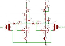
The active loads are MOSFETS; here's a simplified signal path schematic, not showing grid/gate stoppers, etc.
The feedback is a divider from plate to grid, referenced to the input. As a result, input impedance to each stage is relatively low; 2500 ohms for the first stage and about 7K for the second. I'm planning on reducing the first stage Zin to about 1600 ohms which should reduce the input noise somewhat over what I measure now.
This unit is the prototype, and I'm in the middle of working on the noise, so this is very much a work-in-progress.
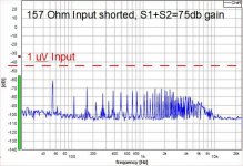
The EIN depends on both the basic amplifier EIN and the switchable input transformer ratio. Here's a sample of what I'm currently seeing at the output referred to the input level, at the 75 dB overall gain setting with 1:4 input step-up ratio . The RMS input noise voltage over 22 KHz bandwidth is about -131 dBu or a little over 200 nV. It's a little less than I expect for what I work out to 150 ohms ENR. Particularly strange that it doesn't look like thermal noise...
Clearly I have some more work to do, with obvious "opportunities".
Cheers,
Michael
Attachments
Last edited:
Michael, with R1 in series with the input signal, what's the point of using a high gm, low Requiv tube in the first stage? R1 totally dominates the noise.
'Noise' looks like 55Hz and harmonics. Funny mains frequency, or narrow LF peak? I suspect the latter. What does the frequency response look like?
Hi Michael,
Thanks for being so open about your circuit design.
MOSFETS in the plate load makes good sense.
The feedback mechanism I am not so sure about. This is basically shunt derived, shunt applied NFB where the input impedance is effectively determined by the input arm of the feedback network i.e. 2K5 on the input stage.
With the transformer input shorted, its secondary is shorted so the only noise source is the 2K5 resistor (plus the presumably small secondary resistance of the transformer) which will produce about 1.1uV of noise. The noise gain with the set up you measured is 75dB minus the 12dB of the transformer or about 63dB. The 1.1uV of noise is about -122dBu so at the output you would expect it to be 63dB higher or -58dB. What you get is about -56dBu or 2dB worse which implies your amp only adds a couple of dB of noise which is very good indeed. You should be able to verify this by repeating the experiment with the transformer secondary shorted which should give a near identical result.
However, the big problem I see with this topology is that you will always have the input resistor contributing to the noise. With your current set up there is also another potential problem. The 2K5 reflected by the 4:1 transformer appears as about 156 ohms at the primary (your note says 157 on the noise graph so I guess I am on the right track). That will be OK for mics with a 50 ohm source resistance but not for 150 ohm mics which will lose 6dB of signal level. For these you will need to change the ratio to 2:1 or even 1:1 to give them optimum loading. This reduces your overall gain by 6 or 12 dB but not the noise gain for the 2K5 resistor so your EIN will get 6 or 12dB worse.
Don't get me wrong, I am not being deliberately critical of your design. It is a topology I have considered myself as it has some key advantages in terms of gain staging that other topologies do not. I am just not convinced of it noise performance.
Cheers
Ian
All great comments which get to the core of the design tradeoffs. Basically, the idea here is that with switchable input transformer ratios, the noise contributed by the input resistor is acceptable. The "real" design is for 1600 ohms instead of 2500 (I just used the resistors I had on hand to get something going) and will have switchable 1600, 400, and 100 ohms input resistances. This gives a theoretical EIN of about -120 dBu at 1800 ohms (assuming 200 Zs), -125 dBu at 500 ohms, and -131 dBu at 133 ohms. It does add a couple of dB noise to mics that are in the 10-12 dB(A) self noise class at typical sensitivities. Whether this is a problem or not depends, but I don't expect a huge issue in most cases.
Another factor is that R1 value decreases at higher gain settings and is only 680 ohms when the stage 1 gain is at maximum of 33 dB. Is R1 effectively in parallel with the feedback resistor?
The whole set of goals and tradeoffs include high gain, good power gain, and headroom (over +30 dBu input level capability) using a simple 2 stage triode circuit. Power gain is useful for driving low impedance outputs. Using D3a tubes I can get good gain margin with a nice triode characteristic and low enough plate resistance to drive 600 ohm loads present on many vintage signal processors e.g. LA-2A or Fairchild 660.
The currently measured "noise" includes excess 60 Hz and multiples thereof; just that the analyzer was apparently confused as to the sample rate. Changing to the proper setting shows the same result with everything lined up on 60 Hz. I should be able to nail this easily.
Cheers,
Michael
Another factor is that R1 value decreases at higher gain settings and is only 680 ohms when the stage 1 gain is at maximum of 33 dB. Is R1 effectively in parallel with the feedback resistor?
The load seen by the microphone is R1 divided by the transformer turns ratio. This means that as you vary R1 to vary the gain, the load seen by the microphone varies. Even if the transformer ratio is 1:1, a 680 ohm load is too low for 150 ohm mics. They like to see a nice constant load of around 1200 ohms.
Cheers
Ian
I should have been a little more clear. R1 and the feedback resistor are both varied together to affect the gain in 3dB steps while keeping the input impedance constant at 1600 ohms.
When the stage gain is at maximum (33db) the value of R1 will be 680 ohms, but due to the larger plate feedback resistance, the input impedance is still 1600 ohms. In this case the ENR should be 680 ohms + 65 ohms for the triode plus a few ohms rbb of the bias transistor + the DCR and reflected source impedance.
Michael
I am struggling to understand this. 33dB is about 45 times so the plate feedback resistance should be in the region of 45 x 680 = about 31K. Since in triode mode, the mu of a D3A is about 80 the feedback resistor 'looks like' 31k/mu from grid to ground or about 390 ohms. This plus the 680 gives an effective input impedance of 1070 ohms, a lot less than the 1600 you calculate. As far as I can see the '65 ohms for the triode' (whatever that means) and the rbb of the bias transistor don't come into it. Or have I missed something??
Cheers
Ian
- Status
- Not open for further replies.
- Home
- Amplifiers
- Tubes / Valves
- Microphone Preamp design