The chart exactly represents what I wrote in post #7, so I agree.I post here two figures from D'Appolito book Testing Loudspeaker to more specifically illustrate the intent of my question.
Based on the Figures, the implication is that based on the distant from the speaker to the microphone, the relative phase difference between the various drivers will change.
The other implication is the further the mic, the relative phase difference is getting smaller and smaller as calculated on the chart. Can everyone agree on this?
The chart represents reality as can be measured or heard at the various vertical off-axis listening positions.
The phase angle changes with the relative vertical off-axis angle.
....The phase angle changes with the relative vertical off-axis angle.
Back to drama.
Yes, some simple parameters in acoustics work just like 7th grade geometry, for example, weltersys's comment.
But this thread started with a question about the coordination of two drivers. And I said, without any intention of being dramatic, that you can't over-simplify the sound output of drivers in this case as if they obeyed simple Euclidean rules.
If they did, when you ran FR plots you'd have hideous nulls showing up when the Euclidean moon crosses the acoustic sun. In fact, you do get interference by the interaction of phases but you don't get nulls.
B.
Last edited:
It is exactly as you concluded and as dr. D'Appolito showed in his simple diagram. You should ignore the individuals introducing unnecessary drama whose only point would seem to be drawing attention.
OK. Thanks. Some have made it more complicated than needed to be.
Ben,And I said, without any intention of being dramatic, that you can't over-simplify the sound output of drivers in this case as if they obeyed simple Euclidean rules.
If they did, when you ran FR plots you'd have hideous nulls showing up when the Euclidean moon crosses the acoustic sun. In fact, you do get interference by the interaction of phases but you don't get nulls.
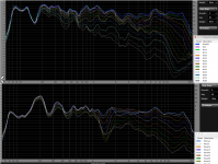
In the polar response charts below, it is easy to see the null in the crossover range deepening between 1kHz and 2kHz as the vertical angle increases thereby increasing the arrival time of the woofer in relation to the tweeter, while the horizontal dispersion, equidistant between the two drivers, stays consistent over the same range.
At a 30 degree angle up from "on axis", that null is around 6 dB deep- whether that is "hideous" is a subjective observation, but it is certainly measurable and can be heard when listening that far off the vertical axis. With the speakers oriented "normally", tweeter over woofer, not a problem when moving laterally, but if the speakers were turned "sideways", the response "suckout" would "suck" by comparison.
Art
Attachments
OK. Thanks. Some have made it more complicated than needed to be.
How you gonna use that information, and why you just picked the simplest answer?
I'm asking this because measuring tape is not valuable (to me) for measuring distance difference of assumed acoustic centers or distance from assumed acoustic center to mic. It's more valuable (to me) for measuring distance from mic to timing origin of driver's measurement data i.e. selected rotation center while off-axis measurement sequence. That is physical origin XO simulators with 3D driver geometry parameters use for timing/phase and SPL simulation of each driver.
You are making two mistakes.Ben,
In the polar response charts below, it is easy to see the null in the crossover range deepening between 1kHz and 2kHz as the vertical angle increases thereby increasing the arrival time of the woofer in relation to the tweeter, while the horizontal dispersion, equidistant between the two drivers, stays consistent over the same range.
At a 30 degree angle up from "on axis", that null is around 6 dB deep- whether that is "hideous" is a subjective observation, but it is certainly measurable....
First, "Null means having no value; in other words null is zero"
Second, although there are dips (of course), but that doesn't mean you or anybody can predict them with a tape measure (AKA Euclidean-like distances), as kimmosto wisely posts and for the reasons I earlier provided.
But your charts do have a dip (reminiscent of stuff Linkwitz published when developing his theories). However, testing two tweeters comes as close to the reductionist situation where even I would expect simple geometry to have a bit of value.
B.
the implication is that based on the distant from the speaker to the microphone, the relative phase difference between the various drivers will change.
The other implication is the further the mic, the relative phase difference is getting smaller and smaller as calculated on the chart.
Thanks.
anyone who has done actual tests will confirm that the phase between the drivers will change when measured at 50cm and then again at 75cm.
unless you have access to a large space measuring an 8ft is not possible.
as a compromise, measure the tweeter at 60cm (or so to get enough data) then lower the mic down to the next driver (whislt maintaining same baffle distance)
Perhaps Dr D'Appolito intended those two figures as a starting point to explore the complexities of any math solution -- and didn't intend to imply that there is an exact, comprehensive mathematical solution.
In any case, it is certainly easy to get lost in the trigonometry ...
If you're still bothered by all this -- that an oversimplification might confound more than illuminate -- keep in mind that Dr's diagrams are only valid if all 3 drivers are getting phase-matched stimuli at all frequencies that they reproduce!
+1 Lojzek
Cheers,
Rick
Last edited:
I think vector summing the height and distance is all that's needed on this level.lost in the trigonometry ...
I am very much challenged in trigonometry and geometry. But I like pictures
Tolvan Data Edge (you can have several sources of same size, same phase), variable baffle, source location, mic position)
Tolvan Data XDir

Tolvan Data Edge (you can have several sources of same size, same phase), variable baffle, source location, mic position)
Tolvan Data XDir
Last edited:
I guess all this hassle starts from selection of design tools and methods which are designed for single mic spot measurements and simulation. Calculations and timing settings are needed to move virtual mic in the simulation to some other location than where actual mic was located while measurement of drivers. For example if all drivers of multi-way were measured at 987 mm to 0 deg and virtual mic in XO simulation is at 2345 mm on tweeter's axis. New calculations and settings are needed if designer wants to move virtual mic to some other distance or elevation. Response is not so correct anymore if driver is simulated to some other off-axis angle than measured. Off-axis simulation needs also reloading measurements.
No one forces to do that, but maybe self punishment is fun and making life of some others more difficult by recommending limited tools and methods is satisfactory. Few examples^
No one forces to do that, but maybe self punishment is fun and making life of some others more difficult by recommending limited tools and methods is satisfactory. Few examples^
I don't think that we have a hassle here, in this thread.
This started as a simple question of one specific phenomenom, how to understand it. Tolvan's Edge and XDir aren't design tools either, but just little visualizers to study a question like the one here.
Basics of an acoustic transducer's behavior in the baffle, off-axis radiation changes per wavelength, interferences with baffle and other transducers etc. must be deeply
understood! Simulations and design programs are combining all this, to the best they can.
Off-axis radiation pattern measurements and simulation is a modern trend, made rather easy by eg. VituixCAD. Designers typically do measurement and simulation to a single distance, typically at approximately 1m because of difficulties of measuring indoors (quasi-anechoic) simulation for design should be optimized at eg. 2,5m.
HiFi Loudspeaker Design
Comb Filtering, Acoustical Interference, & Power Response in Loudspeakers | Audioholics
Sorry, AllenB -- I didn't say that right ..
What I was thinkin' was, "It is awfully easy to find oneself overly invested in the trig -- quite unnecessarily -- considering the many fine, modern tools available."
Apologies ... I'm still trying to learn to write!😉
And Thanks, Juhazi, for a couple of excellent examples.
-R
What I was thinkin' was, "It is awfully easy to find oneself overly invested in the trig -- quite unnecessarily -- considering the many fine, modern tools available."
Apologies ... I'm still trying to learn to write!😉
And Thanks, Juhazi, for a couple of excellent examples.
-R
Last edited:
Measured or simulated vertical off-axis data, few wires and blocks. Driver locations, tilt, delay and other adjustments and that's it.
An externally hosted image should be here but it was not working when we last tested it.
Thx kimmosto! Can you show simulation at 1m vs. 2.5m ?
andy2 post #4 "My real question is that some speakers are measured at say 1meter between the tweeter and mid driver. But there are speakers are measured at listening position such as 8ft length, 37in. height (or somewhere about there)."
andy2 post #4 "My real question is that some speakers are measured at say 1meter between the tweeter and mid driver. But there are speakers are measured at listening position such as 8ft length, 37in. height (or somewhere about there)."
Last edited:
Can you show simulation at 1m vs. 2.5m ?
Practical case is to capture measurement data at 1000 mm and simulate hor & ver planes on spherical surface, radius equals to typical listening distance e.g. at 2500 mm. I don't have measurement data captured at 2500 mm, and simulating directivity to 1000 mm is irrelevant. So my answer is No thanks.
- Home
- Loudspeakers
- Multi-Way
- Microphone position - theoretical phase shift delay