Mostly when I try and move it from service mode 0 to service mode 1, the laser tries to focus and then the CD moves slightly but it drops back to mode 0 again. Occasionally it remains in mode 1 and when in this state I have been able to measure between 48-76mV between TP1 and TP2 (across the 4k7 R3102). With 48mV there is 1.09V at across R3104 (the 18R feeding the laser supply BC338). So it looks like when it works it works (!) but I don't know why it seems to be loosing focus most of the time and dropping back to mode 0. Any suggeestions ?
I have tried to find a schematic of the Micromega Solo and have not been able to locate one which make sorting it more difficult.
I would appreciate it if someone has one or who knows where one might be located!
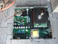
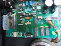
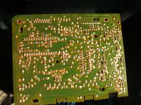
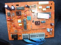
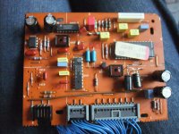
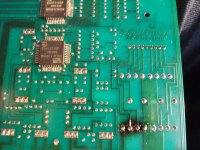
I have attached a pic of the main board - has anyone seen one before? the chips do not seem to ties up with those mentioned
David
check out post #9 about
http://www.diyaudio.com/forums/digi...ega-solo-trio-cd-f1-first-edition-wanted.html
........... Any suggeestions ?
Not really. You say the motor is OK now. Maybe it is just a faulty pickup... I know they are reliable but sometimes it's easy to overlook or convince yourself it's not. If the disc doesn't even spin up to speed (presumably because focus is lost) then it doesn't even get as far as being a "data processing fault" to my way of thinking.
I had a look around the focus circuit with a scope this afternoon, there is significant 100Hz ripple on the FElag pin 😱 so I've taken the main board out and I'm going to work my way back through the power supplies next.
Having removed the bulk caps on the main pcb which are responsible for the CDM-4 supplies ...
Roederstein EKS series 1000uF/25V datasheet spec for ESR 0.19R and today's value 0.66R
Roederstein EKS series 3300uF/16V datasheet spec for ESR 0.08R and today's value 48R 😱 and as if that wasn't bad enough the other one was off the scale ! They should really have fitted 25V parts here 😡
Problem solved 😀
That's brilliant Jon... well done.
You know, when fixing stuff "was the day job" (TV/Video/Audio) I insisted on using a scope for everything. Checking HT rails in TV's etc. You'd be surprised how many weird faults that found. Or running round all the pins on an IC... and seeing the clock or ground or whatever modulated by something. We didn't have the luxury of an E.S.R. meter then 🙂
Happy days though...
Good observations. This observations also of interest for this threads:Having removed the bulk caps on the main pcb which are responsible for the CDM-4 supplies ...
Roederstein EKS series 1000uF/25V datasheet spec for ESR 0.19R and today's value 0.66R
Roederstein EKS series 3300uF/16V datasheet spec for ESR 0.08R and today's value 48R 😱 and as if that wasn't bad enough the other one was off the scale ! They should really have fitted 25V parts here 😡
Problem solved 😀
http://www.diyaudio.com/forums/parts/151392-best-electrolytic-capacitors.html
http://www.diyaudio.com/forums/soli...s-electrolytic-capacitors-audio-circuits.html
I assume, that the term "today's value" is refer to your old and faulty cap devices and not to new cap devices from currently production, what is also not rule-out with cheap manufacturers from China and India.
Correct, "today's value" is what those 20 year old Roederstein's measure today (well yesterday!). Needless to say the Panasonic FC/FM I replaced them with have better ripple current handling and measure better than the Roederstein's did when they were new.
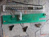
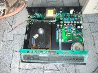
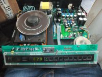
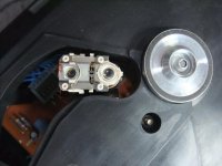
Stripdown/Clean of Micromega's SOLO
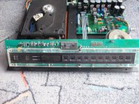
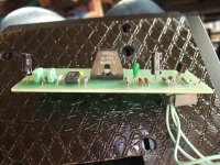
For electrolytic capacitor replacement, troubleshooting and creating schematic a device of this model was completely dismantled and disassembled. several images in follow first from the operating (front) PCB
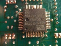
Who know the IR receiver module from image No. 6 ?
Looks similar to those under
https://www.vishay.com/docs/82459/tsop48.pdf
For images of used tactile switch go to
Tactile Switch for Micromega Model "SOLO" and "DUO" first Series
For electrolytic capacitor replacement, troubleshooting and creating schematic a device of this model was completely dismantled and disassembled. several images in follow first from the operating (front) PCB
Who know the IR receiver module from image No. 6 ?
Looks similar to those under
https://www.vishay.com/docs/82459/tsop48.pdf
For images of used tactile switch go to
Tactile Switch for Micromega Model "SOLO" and "DUO" first Series
Attachments


Last edited:
more pics
Attachments
-
 DSCF7232.jpg1,006.3 KB · Views: 203
 -
 DSCF7234.jpg1,008.9 KB · Views: 164
 -
 DSCF7241.jpg992.9 KB · Views: 178
 -
 DSCF7244.jpg1,001.7 KB · Views: 168
 -
 DSCF7246.jpg1,016.7 KB · Views: 201
 -
 DSCF7252.jpg756.4 KB · Views: 181
 -
 DSCF7248.jpg1,015.3 KB · Views: 173
 -
 DSCF7330.jpg1 MB · Views: 215
 -
 DSCF7332.jpg1 MB · Views: 177
 -
 DSCF7260.jpg983 KB · Views: 163
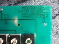
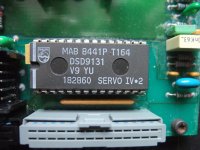
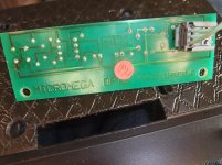
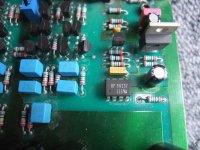
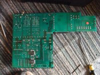
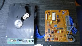
Servo-PCB, OPTO board
Attachments
-
 DSCF7264.jpg887.1 KB · Views: 157
 -
 DSCF7265.jpg990.4 KB · Views: 148
 -
 DSCF7267.jpg778.1 KB · Views: 171
 -
 DSCF7269.jpg992 KB · Views: 158
 -
 DSCF7271.jpg1 MB · Views: 155
 -
 DSCF7274.jpg1,015.9 KB · Views: 142
 -
 DSCF7262.jpg1,005.2 KB · Views: 155
 -
 DSCF7276.jpg1,005.6 KB · Views: 148
 -
 DSCF7298.jpg1,019.3 KB · Views: 146
 -
 DSCF7301.jpg1,017.1 KB · Views: 176
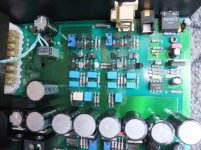
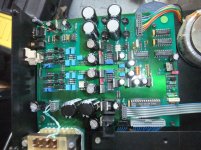
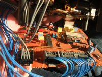
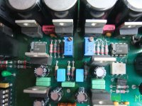
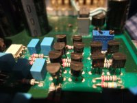
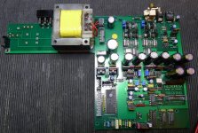
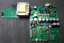
DAC and diamond buffer area incl. burned toroidal transformer for creating 4x 15VDC by voltage regulators 7815 and 7915
Who know the AC voltage (maybe 4x 16VAC) and the VA value so as the A-value of the fuse for primary winding (isn't present in the associated holder at back plate) ?
Thank you for an advice.
P.S.:
As a first attempt, my own circuit diagrams are present but still difficult to read and probably still have many errors. From an other friend I will receive a second device of the same model for preparing for an outdoor power supply. Then I will check the present sketch and make a second attempt for better reading and less errors (for upload here).
Attachments
-
 DSCF7256.jpg992.6 KB · Views: 183
 -
 DSCF7258.jpg998.6 KB · Views: 164
 -
 DSCF7281.jpg983.5 KB · Views: 138
 -
 DSCF7283.jpg1,007.9 KB · Views: 166
 -
 DSCF7287.jpg1 MB · Views: 145
 -
 DSCF7289.jpg1,012.9 KB · Views: 157
 -
 DSCF7291.jpg1 MB · Views: 143
 -
 DSCF7293.jpg879.7 KB · Views: 169
 -
 DSCF7280.jpg1,011.1 KB · Views: 175
 -
 DSCF7278.jpg989.5 KB · Views: 152
Last edited:
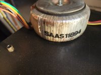
Toroidal transformer and fuses
The secondary of the toroidal transformer measures 4x16V: I can confirm it. I measured it right now. The two original fuses I have on my micromega are 2x 315mA / 250V
The secondary of the toroidal transformer measures 4x16V: I can confirm it. I measured it right now. The two original fuses I have on my micromega are 2x 315mA / 250V
good advice - thank you
some Links to this company:
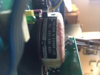
How to read toroidal transformer label
Holden and Fisher transformers | pink fish media
https://www.diyaudio.com/forums/power-supplies/234410-holden-fisher-transformers.html#post6586755
some Links to this company:
How to read toroidal transformer label
Holden and Fisher transformers | pink fish media
https://www.diyaudio.com/forums/power-supplies/234410-holden-fisher-transformers.html#post6586755
images from other device before and after replace electrolytics
Attachments

How often do these toroidal power transformers fail?
In my 50+ year electronics career I have encountered one failure:
A Carver power amplifier where one minute it was fine, then the mains fuse blew, and after that the toroidal power transformer was permanently shorted. I was never able to determine which winding had the short. There were no signs of overheating or physical damage. 10 years later this unit is still sitting on a back shelf somewhere in my audio archive. Also there were no faults in the amplifier circuitry. This amplifier could be restored if a replacement power transformer could be found.
-EB
Last edited:
- Home
- Source & Line
- Digital Source
- Micromega Solo CD Player - help!!