I don't know any well designed, simple all tube circuit that protects from fixed bias output tube runaway, to me, that's enough justification for considering adding a controller. I expect you could do it with discrete solid state circuitry instead.
I know a lot of them - just to mention musical instrument tube amplifiers...
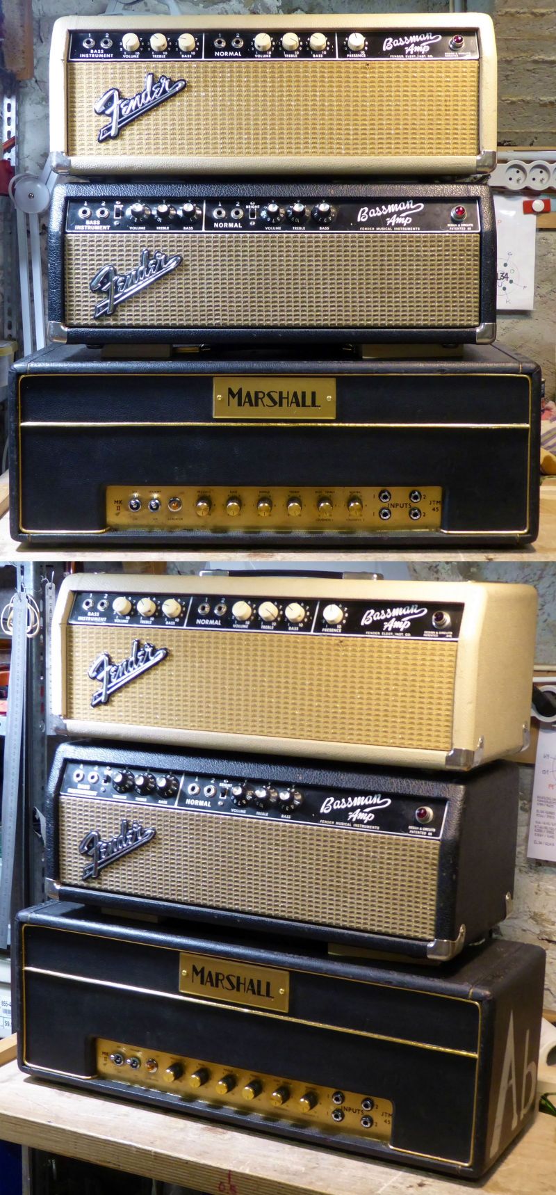
But strangely, these amps are often simple circuits that saw many sets of tubes without issue for years...Here are some below - among many others - that went on my bench from a simple servicing to a restoration due to years of poor treatment : Two Fender Bassman 6G6-A and a Marshall JTM45 from 1964.
All of them are fixed bias, and use a push-pull of 6L6GC tubes for a 45WRMS output measured before onset of clipping, with no other protection than their fuses. Still working fine, since the early 60s. No overheat, no runaway :
Now look at those ones below : 3 Ampeg SVT (300WRMS)
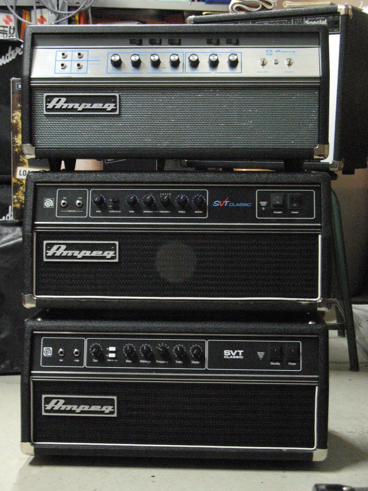
The upper one is a 1972-73 one, commonly called "The Rolling Stone" tour associated model.
The middle one is a 1990s, made in USA model.
The lower one is a Vietnam made 2000s model.
All three are concert / backline rental equipment. Guess what ?
The middle and lower one both suffer regularly from their biasing / checking / protection circuits, burning tubes (6x6550) prematurely because it is an unstable and drifting design.
The first one has a simple, classic bias circuit, no checking, no blinking leds, no voltage comparators, no software : you open the amp, set it up with your DMM after running-in, and it work reliably and flawlessly until its tubes reach their end of life.
If the tube amp circuit is well-designed, you don't need additional circuits. The problem is that most of the tube amps of today are not : pushing their tubes too far, fragile PC-like circuitry, etc... Then you add a microcontroller or any special security device like a patch, a bandage. And what's more, it looks modern and salesy : it's a progress, isn't it ?
But when you have vintage and well designed circuits on hand, you end to understand where's the failure !
T

Depends on the amp; some from yesterday did the same, all in an effort for that competitive edge. Your presented "collection" is certainly drool-worthy!pushing their tubes too far,
My previous post came out of being an "instrumentation engineer" and working for 20 years using LabView, which allowed easy construction of control / readout / analysis graphical User Interfaces. Basically a PC based programming IDE that worked well with the hardware they sell. The trick was to get it to work with the hardware you happened to have on hand; I was by no means expert at that!
Fast forward 30 years and one would think some ARM based SBC running Linux - talking to much, much cheaper, multifunction interface cards - could easily handle it. Or directly to chips via I2C...
A step further - screw the on-amplifier screen - the amplifier should be just like your router or NAS; puts up a web page graphical interface after connecting wirelessly via DHCP to your home network. With pages of information and settings. Every router and NAS has this, so some people know how to do it, without resorting to a LabView IDE.
Check that you actually remembered to turn the amps off one morning, while driving down the road (in your ride to work car pool) from your cell phone.
Many old amps and many new amps could indeed run forever until "its tubes reach their end of life."I know a lot of them - just to mention musical instrument tube amplifiers...
The middle and lower one both suffer regularly from their biasing / checking / protection circuits, burning tubes (6x6550) prematurely because it is an unstable and drifting design.
.....it work reliably and flawlessly until its tubes reach their end of life.
Most vacuum tubes made 50 years ago reached "end of life" when their cathode emission became too low to support proper operation of the device that it was installed in.
Unfortunately that's not always the case with some of today's current production tubes. Many exhibit signs of "gas" when new, and this will increase with use. A class A SE amp is usually worse case since the tube sits at 70 to 90% of its rated dissipation all the time. Run a new production tube like that daily for a year or two and a small percentage of them will develop bias creep where the idle current slowly increases due to gas causing grid current which bleeds off some of the grid bias. A percentage of these tubes will eventually go into red plate runaway. Usually this causes audible distortion before damage occurs, but several cathode biased SE amps with New Sensor KT88's or 6550's in them have progressed to blown line fuses, cathode bypass caps, and or cathode resistors.
Every amp builder or service tech has their own ideas about how to handle this situation, but I will implement some sort of non intrusive detection and shutdown to prevent a possibly expensive event in an amp that can consume nearly 2 kilowatts of power in normal operation. If such an event never happens, then at worst I invested $30 extra and some programming and interface design time, which is a learning experience, worth the $30 in my book.
Another situation that is very real in the musical instrument amp world, is "Crank the SVT to full power into some crappy 2 X 15 cabinet that was never meant to eat 300+ watts," or something similar. Sooner or later the speakers will blow into an open circuit leaving the amp unloaded at full power. I got to fix an SVT that I watched this happen to from the audience back in the 70's. It needed an OPT a tube socket some new tubes, and a bunch of other parts. The plate to heater winding arc that burnt one of the octal sockets also blew the heater in a 12AX7! I plan to test under exactly this scenario with a lower power (50+watts with cheap 6L6GC's) amp and some "sacrificial" OPT's. In a guitar amp build in the near future. If I can offer some protection with a microprocessor, again, why not?
When the microcontroller board goes into the guitar amp it will be used to store and recall settings. Back in the late 1990's I made two solid state guitar amps that used some chips that I got from the National Semiconductor sales rep. One was for his kid. The amp used a PIC chip and an EEPROM that could control the tone and gain control chips over the SPI bus. It was a neat idea, but didn't do screaming rock guitar well. I also have an old ADA MP-1 that uses a really complicated 8 bit computer to store settings. I will attempt to implement a modern day version in a tube amp using a 32 bit Teensy.
I know a lot of them - just to mention musical instrument tube amplifiers...
That's a nice pile of amps, for sure. Heads rather than combos, that should help their reliability. I have more experience with hifi amps than instrument amps, but I do understand it is typical to bias more conservatively with instrument amps (60-70%) vs. 90% for a hifi amp. I've run mostly Dynaco fixed bias amps for 45 years or so, and probably have had 5 or so output tubes red plate in that time. I would also favor not using bias protection on the instrument amps, but I like the idea for hifi to squeeze out the last bit of power and reliability.
There's a good use case for "management" circuitry. Depending on if there's any music going into the amp's inputs. In my history of tube amp for stereo listening, they've all accumulated more hours at idle, than actually listening to music. A simple watchdog would have been appreciated, as part of the amp's functionality.A class A SE amp is usually worse case since the tube sits at 70 to 90% of its rated dissipation all the time.
One time I tried to use home automation controlled AC wallwarts to turn the amps on. Nope. Came home from work; just one was on the other off. Now the two amps have some imbalance of hours on the tubes...
Makes you wonder if some kind of MOV or transorb device could be of any use, limiting the primary reactive voltage before it can jump pins on an octal socket. Like, have a low value resistor on the output winding, that only kicks in above some voltage higher than the amp would produce loaded. Enough? Or better than nothing...Sooner or later the speakers will blow into an open circuit leaving the amp unloaded at full power.
Hi ReactanceA well-designed reliable system enables an MCU to reference a +HV line through the use of isolation amplifiers or something equivalent (mini transformer), ensuring galvanic isolation between systems is maintained. This setup allows the entire MCU I/O and ADC to operate independently, with the capability to send shutdown commands to deactivate the PSU live. Additionally, this means the MCU is powered by its own 5W/5V transformer or PSU, making the system fully independent.
I agree sometimes total galvanic isolation is necessary especially if there is to be a hard wired connection to the outside world. A small power transformer for the micro PCB is a good idea especially if one wants remote control. I once made a small tube tester, curve tracer that simply used blue tooth for data and a small LCD, no galvanic isolation was employed internally, the device was powered from 12VDC and used a pulse testing technique for the tubes. The bluetooth connection was the galvanic isolation.
I don't have a problem measuring B+ through a high voltage rated 10 meg resistor if there are no external connections to the outside world.
More chips like the MAX22530 would make life easier, I like the built in isolated supply. I have never tried this chip and have not read the entire data sheet, the concept seems good.
BTW lots of galvanic isolation was used in my last tube tester.
That would be a very interesting case for the use of a microprocessor alright. Would you use it to shut down the output section when it detects an open circuit after the OPT? That would be my first instinct. I wonder what the best way to implement that would be.If I can offer some protection with a microprocessor, again, why not?
+1 for the Pi Pico. A nice board, a bit similar to the MBED boards. Once I got the Arm toolchain working on my Linux, it's just a matter of compiling something in c++ and uploading a file into the pico's USB drive. There's debug option that bypasses the USB, but I haven't looked into it yet.
Since I'm a newb when it comes to tubes, I'm looking at building a hybrid power amplifier with the simplest possible triode (or nutube?) pre-amp stage, but pairing that with a MOSFET push-pull output stage, specially configured for mixed-mode output impedance. The usual (guitar amp) approach for mixed mode seems to put the speaker in the feedback path at high frequencies, so I want to avoid that.
So I'm wondering out loud if there's an opportunity to have distortion cancellation in open loop? E.g. the MCU adjusts the tube pre-distortion so it's the inverse of the output stage distortion. An unknown, as yet is if a triode load line can be shaped to cancel push-pull distortion, or if it's more adding the missing even harmonics between the odd ones? It's just an intellectual exercise at the moment, but I might be motivated to build something if it seems promising.
What design are you using for this? Just out of curiosity. I want to build a solid-state output that behaves like a tube power section, and I'm, "shopping around," for the best DIY project hahabut pairing that with a MOSFET push-pull output stage, specially configured for mixed-mode output impedance
Attempting to detect an open circuit in a live circuit with varying voltage levels is difficult and unpredictable at best. Many guitar amps attempt to use reverse biased silicon diodes in an attempt to clamp the voltage at the output tube plates to 2X the B+ voltage. This will work to some extent in a HiFi amp where operation in severe clipping is not part of "normal operation." That is not often the case with a guitar amp.That would be a very interesting case for the use of a microprocessor alright. Would you use it to shut down the output section when it detects an open circuit after the OPT? That would be my first instinct. I wonder what the best way to implement that would be.
While working in a "think tank" group in the 1990's I had an opportunity to develop some lightning protection for a wireless irrigation control system used on golf courses and similar environments. I used an old cardiac defibrillator to simulate lightning strikes, and successfully developed some circuitry that could eat my DIY lightning bolts. One of the key components was a "gas discharge surge arrestor" component. It's basically a high current neon lamp that can eat a lot of energy for a very short time. These emit a flash of bright blue to white light when breakdown occurs. That flash can be used to trigger a circuit that shuts down the amp, with or without a microcontroller. The fastest way to shut down a serious event is to remove the screen grid voltage from the output tubes.....unless a tube arc has already started. Some serious experimentation will be needed here. This was mentioned in post #27 here:
https://www.diyaudio.com/community/...-a-stupid-question.408737/page-2#post-7593786
The slick sheet for the irrigation controller is here. Scroll down to see the features list. Guess who invented the one on the left back in 1994?
https://www.toro.com/en/product/E-Series-Osmac
This has been discussed several times in the past:
https://www.diyaudio.com/community/...-a-stupid-question.408737/page-2#post-7593786
https://www.diyaudio.com/community/threads/tube-output-protection.180744/
Last edited:
I find the ESP32's provide the best bang for the buck. I don't waste my time with the ATMega/MInis/Micros because they run out of code space quickly.
I only use them for the simplest projects.
The S2 minis are very capable and are now my goto for most projects.
https://www.amazon.com/HiLetgo-ESP32-S2FN4R2-ESP32-S2-Type-C-Connect/dp/B0B291LZ99
Easiest way for wifi control is to set the ESP32 up as a wifi hotspot and then use a web interface for controls.
You won't have to write a cell phone app with this approach.
Another nice thing is that you can easily perform over the air software updates with the ESP32. Very useful if you ESP32 board is embedded into a project and is actually much easier than connecting a USB cable.
The relevant libraries to use are up on github.
"ESPUI" - Provides web based controls, slide controls, switches, text input, etc...
"ESPOTA" = Wifi software updating
Both libraries provide excellent examples and are easy to use.
The downside with the Arduino IDE with ESP32 on WIndows is that it compiles slow. However it goes much faster under Linux, even inside a Virtual machine on Windows.
If you need more info give me a buzz.
Yeah I don't think I'm fitting one of those in a guitar amp!!Attempting to detect an open circuit in a live circuit with varying voltage levels is difficult and unpredictable at best. Many guitar amps attempt to use reverse biased silicon diodes in an attempt to clamp the voltage at the output tube plates to 2X the B+ voltage. This will work to some extent in a HiFi amp where operation in severe clipping is not part of "normal operation." That is not often the case with a guitar amp.
...
The slick sheet for the irrigation controller is here. Scroll down to see the features list. Guess who invented the one on the left back in 1994?
https://www.toro.com/en/product/E-Series-Osmac
I'll have to do a lot more research into this topic before I actually implement a solution like this. Strapping random **** across the output of a OPT sounds like a brilliant way to set things on fire.
That looks really promising alright. I do wonder about putting a wifi enabled microprocessor inside of a tube amp though, considering my general rule of thumb is to keep as much potential radio interference OUT of a signal path 🙂I find the ESP32's provide the best bang for the buck. I don't waste my time with the ATMega/MInis/Micros because they run out of code space quickly.
I only use them for the simplest projects.
Out of curiosity, what solutions have you implemented using this (the microcontroller) in the past?
"Yeah I don't think I'm fitting one of those in a guitar amp!!"
The green enclosure in the picture is the outer protective housing that a smaller beige box drops into. You don't put expensive electronics on a golf course and not expect them to be attacked by golf balls, golf carts, angry golfers that already have a club in their hands, and even alligators. Yes, gators on a golf course in Florida is not uncommon. Does lightning strike golf courses in Florida? Either way I was referring to the protection circuitry that I designed for the input board that connected to buried wiring on the golf course. Burnt boards were common.
"Strapping random **** across the output of a OPT sounds like a brilliant way to set things on fire."
The key element in the protection scheme was the Gas Discharge Tube arrestor. These things are about the same size as a 2 watt carbon comp resistor, though a bit shorter. They can often survive a lightning strike even though the PC board that they were on didn't. They come in breakdown voltages from 75 volts to 3000 volts. The idea is to pick a voltage that will not be seen in normal (clipped, cranked to 11) operation, but below the breakdown voltage of the OPT. I doubt that a tube amp / OPT combo has enough stored energy to blow these things, but I will get some and find out. The issue arises from continuous operation in breakover where these devices will overheat. That's where the light sensor comes into play.
https://www.digikey.com/en/products/filter/gas-discharge-tube-arresters-gdt/142?
The form-factor of ESP32 development PCB board might be an issue. If it is embedded in a metal chassis, it might require an external antenna. ESP32 can multitask but compiled with Arduino libraries runs in a single Task. It is not obvious that you can do a modular design with multitasking by calling core ESP32 functions,.The downside with the Arduino IDE with ESP32 on WIndows is that it compiles slow. However it goes much faster under Linux, even inside a Virtual machine on Windows.
Not really. I'm pretty certain an adjustable bipolar "zener diode" could be made with FETs, that could clamp a 4 Ohm across the speaker output, should it see a peak voltage > what it's ever supposed to be when properly loaded with speakers. Pretty quickly too. Hopefully the player would notice "no sound" and stop playing, before the clamp resistor burned up. Latching operation, of course.Strapping random **** across the output of a OPT sounds like a brilliant way to set things on fire.
Regarding "Gas Discharge Tubes", these are the equivalent of a spark gap. I have successfully used them to protect wind turbine electronics. Once fired the remain at a very low resistance until the correct conditions are met to extinguish them so never plate to ground, plate to plate or across the output transformer is a possible location. Referring to "An Approach To Audio Frequency Amplifier Design" GEC 1957 https://pearl-hifi.com/06_Lit_Archive/15_Mfrs_Publications/GEC_UK/GEC-UK_AF_Amplifier_Design.pdf is a good read. Read pages 86 and 87. While repairing tube amplifiers in the 70's and 80's in Aus and NZ I never found a burnt tube socket or damaged output transformer in a spark gap equipped amplifier. I did however see signs the spark gaps had been firing. For the occasion when someone strums a guitar with low volume and an open circuit lead I could see a micro shutdown working. I have seen people crank the volume up and keep trying while looking for a fault before the smoke and nasty noises. I think a Gas Discharge Tubes would have it's place, almost no capacitance and almost invisible until it fires. A single firing of the GDT could send a pulse to the micro controller and even operate a fast protection device."Yeah I don't think I'm fitting one of those in a guitar amp!!"
The green enclosure in the picture is the outer protective housing that a smaller beige box drops into. You don't put expensive electronics on a golf course and not expect them to be attacked by golf balls, golf carts, angry golfers that already have a club in their hands, and even alligators. Yes, gators on a golf course in Florida is not uncommon. Does lightning strike golf courses in Florida? Either way I was referring to the protection circuitry that I designed for the input board that connected to buried wiring on the golf course. Burnt boards were common.
"Strapping random **** across the output of a OPT sounds like a brilliant way to set things on fire."
The key element in the protection scheme was the Gas Discharge Tube arrestor. These things are about the same size as a 2 watt carbon comp resistor, though a bit shorter. They can often survive a lightning strike even though the PC board that they were on didn't. They come in breakdown voltages from 75 volts to 3000 volts. The idea is to pick a voltage that will not be seen in normal (clipped, cranked to 11) operation, but below the breakdown voltage of the OPT. I doubt that a tube amp / OPT combo has enough stored energy to blow these things, but I will get some and find out. The issue arises from continuous operation in breakover where these devices will overheat. That's where the light sensor comes into play.
https://www.digikey.com/en/products/filter/gas-discharge-tube-arresters-gdt/142?
BTW I've seen spark gaps on very large modulation transformer.
I'm presently working on a GPS based speedometer kit. It is intended as an upgrade for vintage vehicles. The unit is configured via a web interface as well as accessing extended features.Out of curiosity, what solutions have you implemented using this (the microcontroller) in the past?
I think I mis-communicated on my comment on adding stuff to an OPT. I referring to myself not understanding this topic very well, and I want to be well informed before I implement a permanent solution on any of my builds! Thanks for the information so far. I do not pretend to be more knowledgeable than people who have been doing this stuff professionally for twice as long as I have been alive 🙂 apologies if I came across stand-off-ish!
Is this something that should be measured or calculated? How would one go about doing this?The idea is to pick a voltage that will not be seen in normal (clipped, cranked to 11) operation, but below the breakdown voltage of the OPT.
I'm assuming this is a similar idea to the gas discharge tube?I'm pretty certain an adjustable bipolar "zener diode" could be made with FETs, that could clamp a 4 Ohm across the speaker output, should it see a peak voltage > what it's ever supposed to be when properly loaded with speakers.
A WiFi enabled chip does indeed sound like a perfect solution for such a project. I personally would stick to wired connections inside something like an instrument amp, but that could easily be me being paranoid about noise issues.I'm presently working on a GPS based speedometer kit. It is intended as an upgrade for vintage vehicles. The unit is configured via a web interface as well as accessing extended features.
If you are worried about RFI, you could cut the PCB antenna trace on the ESP32 board and solder on some thin coax and run to a short 1/4 wave antenna outside of the box. Probably a good idea to get good connectivity range anyhow.
I don't think you'll have troubles otherwise, lets face it - you don't hear Wifi RFI on you laptop speakers do you?
I did put an Arduino Pro Micro (without WIFI) inside my Hafler IRIS pre-amp in order to implement my own IR remote control solution. Like yourself I was concerned about the micro's oscillator clock somehow radiating into the pre-amp, but there were no problems.
- Home
- Amplifiers
- Tubes / Valves
- Microcontrollers in tube amplifiers