Is there a place for a dedicated thread on Micro Controllers In Tube Amplifiers? If there is no interest the thread will die.
I was reading the thread by jcalvarez on Hybrib Bias For Output Stage, and a comment by Chris about servo bias made me think of using a micro controller.
I have been tempted to use a PIC micro as a set fixed-bias device as it could also function as a fault detector possibly operating a SCR crowbar fuse type emergency shutdown on the on the B+. One micro could monitor all the tubes in the amplifier, better to blow a fuse and flag an error rather than damage expensive components.
I'm certain many forum users are very skilled in the use of micros and programming.
Maybe some readily available boards like the Arduino range could be employed and be powered from the heater supply, code and designs could be shared.
Rather than over complicate the amplifier it may be possible to protect some expensive hardware relatively cheaply.
Some possibilities:
shorted tube detection
arc detection
set bias
flag weak out of spec tubes
auto shut down after inactivity
emergency SCR shutdown
detect shorted/overloaded/open circuit output
clipping indication maybe a LED
B+ delay (relay)
soft start B+
RF detection
low/high voltage mains detection
faults could be flagged and saved to eeprom, fault codes could be cleared by pushing a button.
For a simple device no programming approach trim pots could set bias and other parameters.
Maybe someone could write a phone app.
If Arduino was used the program parameters can be edited using free software. Arduino use C++ I think.
As far as possible the designs could be fail to safe.
ESP32's seem to be fashionable at the moment, I believe one can use the Arduino IDE.
Some PIC's have stood the test of time and seem to be very good, a custom board would need to be made. There is free software about for programming PIC's (C and BASIC).
Custom PCB's would be the best approach. The board could be relatively simple to install and should not impact the sound quality apart from precise the auto bias as the tubes age. Bias information would be held in eeprom.

Is there a place for a dedicated thread on Micro Controllers In Tube Amplifiers? If there is no interest the thread will die.
I was reading the thread by jcalvarez on Hybrib Bias For Output Stage, and a comment by Chris about servo bias made me think of using a micro controller.
I have been tempted to use a PIC micro as a set fixed-bias device as it could also function as a fault detector possibly operating a SCR crowbar fuse type emergency shutdown on the on the B+. One micro could monitor all the tubes in the amplifier, better to blow a fuse and flag an error rather than damage expensive components.
I'm certain many forum users are very skilled in the use of micros and programming.
Maybe some readily available boards like the Arduino range could be employed and be powered from the heater supply, code and designs could be shared.
Rather than over complicate the amplifier it may be possible to protect some expensive hardware relatively cheaply.
Some possibilities:
shorted tube detection
arc detection
set bias
flag weak out of spec tubes
auto shut down after inactivity
emergency SCR shutdown
detect shorted/overloaded/open circuit output
clipping indication maybe a LED
B+ delay (relay)
soft start B+
RF detection
low/high voltage mains detection
faults could be flagged and saved to eeprom, fault codes could be cleared by pushing a button.
For a simple device no programming approach trim pots could set bias and other parameters.
Maybe someone could write a phone app.
If Arduino was used the program parameters can be edited using free software. Arduino use C++ I think.
As far as possible the designs could be fail to safe.
ESP32's seem to be fashionable at the moment, I believe one can use the Arduino IDE.
Some PIC's have stood the test of time and seem to be very good, a custom board would need to be made. There is free software about for programming PIC's (C and BASIC).
Custom PCB's would be the best approach. The board could be relatively simple to install and should not impact the sound quality apart from precise the auto bias as the tubes age. Bias information would be held in eeprom.
I did this for a class-D amplifier with comparable features, my only recommendation now is to set aside Arduino for projects requiring real-time control with the fastest response times. Instead, opt for ARM 32 or PIC16/18/32/dspPIC, working directly with C on the bare metal ASM (no C++). By thoroughly understanding the MCU peripherals and fixed point numbers helps alot, you will need a good analog isolated interfacing solution for HV, you can develop a system capable of cycling through all protection functions in less than 100 microseconds and shutdown command in under 10us.
Arduino is currently the most popular microcontroller, offering a range of microcontrollers such as ESP32. The programming language used by Arduino is a variant of C, but C++ is also compatible. You can use the Arduino IDE, which is either PC-based or cloud-based. To develop a human machine interface (HMI) for your project, you can use Arduino Cloud or Blynk for smartphone integration.
If you want to achieve fast response times, you need a microcontroller. Microprocessors like Raspberry Pi do not operate in real-time and multitask a variety of apps and support programmes. Microcontrollers, on the other hand, are capable of reacting quickly. If you need multitasking, you can feed the microcontroller to the microprocessor, USB, and share data. For example, you can connect an FM tuner microcontroller to a Raspberry Pi and write a Python program with a Q interface running on the desktop that you can remotely access from a Windows 11 computer.
To monitor voltage levels, use voltage divider circuits to drop the monitoring voltage to an acceptable range for an Arduino analog input. Then, write code to react to various levels and assign the result to a variable that is linked to Arduino Cloud or Blynk. You can access the HMI on your Android or Apple cell phone, as well as any tablet or computer with access to the internet. You can also have analog or digital inputs and outputs to manipulate the project.
However, if you are controlling a circuit, such as a DC relay, you may encounter issues due to the Back EMF of a DC relay, which generates a spike that is 10 times the control voltage or more in the negative direction. To short-circuit the spike, put a diode across the coil, but even then, you should not expose the microprocessor to this (harmonics). Optoisolators are used to isolate the input on a per-case basis.
One thing you didn't mention in your list is to ramp up the voltage slowly when turned on. For example, you can control the start voltage, the end voltage, and the timebase for the slope of an SCR on the mains feeding into the power transformer, slowly increasing the voltage and allowing the tubes to heat up in a controlled fashion and monitor critical points for an emergency shutdown. A smart built-in variac. The harmonics generated by the SCRs are naturally removed in the power transformer and the secondary capacitors.
I want to automate the process of testing tubes and use a microprocessor driving an HMI touch display. You can mimic the slide switches and monitor the analog voltage going into the meter. I use the Lafayette 99-5063 and it takes time to set up. I'd scan the tuning charts for the various tubes into a comma delimiter list and convert it into a lookup table as a 6-element array. The first element would hold the tube number as a string. All I need to do is punch in the tube.
Finally,
In return for this reply, I'm interested in preamp (tone control) and amplifier schematics for 12 AU6 and 12AT7 tubes.
try a PM to Mr. Anderson (TubeLab) Had an article published in an audio mag years ago using (I think) pic controlers
Not a tube guy, but just discovered the pi-pico, which is a uC from pi foundation. Board is very inexpensive, 4 bucks. I use a pi-4 for development and then download the code to the pico. I believe it is a dual core 125MHz arm processor. No floating processor though, so float ops are done in software. The builtin A/D is not great either but depending on application, may be good enough without needing to add an external I2C or SPI one. Pico supports both I2C and SPI in hardware. I've even managed to get it to be an SPI slave to a pi, and then it handles sampling as an SPI master at a very high rate at a very solid interval. I find it pretty zippy and as others have said, no O/S to get in the way.
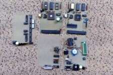
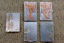
I have been sticking microcontrollers into projects since I made a crude "chiptune" music synthesizer with my SWTPC 6800 computer in 1976. There are two pictures from some DIY "maker computer boards" I built in the early 90's that I dug out of a long lost box a few years ago. I used derivatives of the Motorola MC68HC11 chip for two of those. The unmarked window chip is a pre-production sample part.try a PM to Mr. Anderson (TubeLab) Had an article published in an audio mag years ago using (I think) pic controlers
The article was in Circuit Cellar magazine back in October of 2008. Circuit Cellar was a "maker" type of electronics magazine with a heavy emphasis on microprocessors, microcontrollers and small form factor "maker" CPU boards back before Arduino existed. They are still publishing today. They often ran contests sponsored by manufacturers. This article was my entry into a contest that was sponsored by Microchip, who makes the PIC chips. The article is included here. I dug the old boards out of the same box that the DIY maker boards came out of and I'm trying to figure out what I did over 15 years ago. I know that the concept was borrowed from some work I did at Motorola on efficiency improvements in linear RF power amps for cell towers.
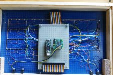
My choice for microcontroller boards today where processing power is important (mostly music synthesis) is the Teensy series from PJRC. These are small boards with a 32 bit ARM Cortex M7 chip with FPU running at 600 MHz, overclockable to near 1 GHz. The two pictures show a "virtual analog" music synthesizer that I built with a Teensy 3.6 board about 7 years ago. it is now part of my "wall of synth" where it can be controlled via MIDI or CV/Gate.
Attachments

I keep planning to integrate a arduino like thing with a tube amp (or a tube tester), but other projects keep getting in the way.
About the arduino 'sketch' programming language: I was a little put off at first, because I thought is was some crippled version of C, which I didn't want to deal with. A little research told me it IS real C++ (derived from the g++ compiler I think) with handholding in mapping ports, startup code and the like. You don't get libstdc++ or any other libraries, so you'll probably have to roll your own math functions and such. The arduino 'sketch' system is just a preprocessor that generates startup code and calls user supplied setup() and loop() functions. The generated setup, library code to deal with displays and such, and simple wiring to a pre-assembled board in my mind makes the arduino a big win for DIY projects (the difficult and time consuming parts are already dealt with). Running at whatever Mhz they run at will be plenty fast for controlling a tube amp.
About the arduino 'sketch' programming language: I was a little put off at first, because I thought is was some crippled version of C, which I didn't want to deal with. A little research told me it IS real C++ (derived from the g++ compiler I think) with handholding in mapping ports, startup code and the like. You don't get libstdc++ or any other libraries, so you'll probably have to roll your own math functions and such. The arduino 'sketch' system is just a preprocessor that generates startup code and calls user supplied setup() and loop() functions. The generated setup, library code to deal with displays and such, and simple wiring to a pre-assembled board in my mind makes the arduino a big win for DIY projects (the difficult and time consuming parts are already dealt with). Running at whatever Mhz they run at will be plenty fast for controlling a tube amp.
ESP micros are WiFi beacons by default. However, there is a WiFI method to turn WiFi off such that you are left with a micro faster than some of the Arduinos. If you only need a few GPIO than NodeMCU (ESP8266) will do. If you need many pins, then use ESP32. You can program using the official Espressive software. But Arduino IDE is easier. I use PlatformIO which wraps the Arduino libraries.
Many people here know that I worked at Motorola for 41 years. I started on the assembly line in 1973 with zero formal electronics education and made my way into engineering in 1984. Sometime around 1990 I was offered a deal to go to college for an "engineering" degree at Motorola's expense. I settled on a computer engineering degree at a small private school based mostly on the fact that it was close to home. The CE degree encompassed some of the basic EE courses with a bit of computer hardware and lots of programming classes. I had a couple of brilliant teachers for most of the programming classes, and they understood that I had no intention of writing code for a living, I just needed the degree. With their help I invented a language we called C--. Basically, C with all the hard stuff left out. I could create some large programs that might have called a few functions, but mostly just executed a large loop. Today we would call them Arduino sketches. The Teensy modules that I spoke of earlier didn't exist then, but I found them through the music synthesizer world because of the large drag and drop audio library that creates the hard code for you. There is a companion audio interface board that does stereo audio in and out at 16 / 44.1 that works with their library.
If you need to play with audio and 44/ 16 is good enough, the Teensy might be a good choice. Unfortunately, the 3.X boards had a 16 bit A/D but are now extinct since the Freescale chips were discontinued when NXP ate the company. The 4.X boards are faster but cost a few $ more and have only a 12 bit A/D.
If you need to play with audio and 44/ 16 is good enough, the Teensy might be a good choice. Unfortunately, the 3.X boards had a 16 bit A/D but are now extinct since the Freescale chips were discontinued when NXP ate the company. The 4.X boards are faster but cost a few $ more and have only a 12 bit A/D.
I actually speak C-- quite well. There have been some great answers in this post so far, as expected there are some experts on the forum.
I have made a few tube testers in the past and complexity often becomes a little overwhelming with lots of components to load. Regardless of the accuracy of the neg bias circuit a bias voltage monitor always seems to creep into the design with this in mind and the fact that four bias adjustment circuits may be require here is todays version. It requires a regulated +5V rail, a regulated -100V rail maybe a quad DAC and a quad FET opamp (5V single rail RR/IO ). Never built, food for thought. I expect a small bias voltage change with temperature, as the bias voltage is monitored this should not be a problem. Obviously more components will make it better. C1 is small as a 1kHz sine wave is used to demonstrate operation.
The entire device could be on a single PCB with a quad ADC and a quad DAC with I2C or whatever for data. R2 could be placed externally near the grid.
Attachments
Rather than over complicate the amplifier it may be possible to protect some expensive hardware relatively cheaply.
Some possibilities:
shorted tube detection
arc detection
set bias
flag weak out of spec tubes
auto shut down after inactivity
emergency SCR shutdown
detect shorted/overloaded/open circuit output
clipping indication maybe a LED
B+ delay (relay)
soft start B+
RF detection
low/high voltage mains detection
faults could be flagged and saved to eeprom, fault codes could be cleared by pushing a button.
I personally would not rely on a microcontroller circuit to "manage" a tube amplifier : I would be very afraid that it would be THE source of failure itself !
OK, I must confess that I am very far from being an Arduino or C++ ace or even a fan, but IMHO, and by my experience, a well-designed tube circuit has absolutely no need of such additional complications...
But it's me, OK ?
tubelectron
While I agree with your statement
"I personally would not rely on a microcontroller circuit to "manage" a tube amplifier : I would be very afraid that it would be THE source of failure itself".
A well designed microcontroller controlled and monitored tube amplifier should fail-to-safe.
While I agree with your statement
"I personally would not rely on a microcontroller circuit to "manage" a tube amplifier : I would be very afraid that it would be THE source of failure itself".
A well designed microcontroller controlled and monitored tube amplifier should fail-to-safe.
tubelectron
While I agree with your statement
"I personally would not rely on a microcontroller circuit to "manage" a tube amplifier : I would be very afraid that it would be THE source of failure itself".
A well designed microcontroller controlled and monitored tube amplifier should fail-to-safe.
Yes @Tubekwk, possibly : otherwise the PIC, Arduino, BlackBerry modules wouldn't be so popular. The major problem is : if well designed. That's like Tube Amps : if well-designed, they don't need anything to control and monitor them. But how many are ? 😕
I have repaired so many Tube Amps (Hifi and Bass or Guitar of the "recent" era) where the failures were caused by solidstate circuits of all kind : regulators, FET drivers, automatic bias control and warning, timers, channel switching, etc. 🙄
If I see a defective Tube Amp with a microcontroller inside coming in for repair, I'll certainly be reluctant to intervine on it : this type of "Tube-SolidState-Software" marriage inspires much precariousness and suspicion in me ! 😉
T
I guess I could imagine one with a touch screen. The UI would have to be really good
Touch one of the the tubes in the UI image and a little chart pops up with all the requisite voltages and currents. Flip over to the power supply UI, set and see 3-4 B+ rails and the screen voltages, see an oscillograph of the voltage ripple on the main B+ output. Flip over to the output tube page, see graphs of the calculated transconductance over time for each tube since the last set was installed. Play with the time constants of the bias servos that set each tubes quiescent current independently. Set the operating mode of the tubes (Requires a B+ power cycle). Go back and play with the power supply voltage settings to better accommodate that change, modifying the values from what was last saved for that mode. Question yourself on the power up / down B+ sequence you've got programmed.
When you get every available parameter (Some extra $) how you want, go to the player screen, pick something out, set the volume sit back and try to enjoy. ( Get your hand lightly swatted by your wife for attempting to touch the screen again. )
I would seriously consider a microcontroller in say, a 1 KW tube amp that consumes about 1.8 KW of power at full output. In this case a simple gassy tube runaway event in an amp that uses 6 X tubes in each channel, and each is RATED for 1.4 AMPS of cathode current can fry some pricey, and now unobtainable OPT's before the fuse blows. I consider at a minimum cathode current monitoring in each of the 12 output tubes with auto shutdown of the entire amp if one goes out of bounds in the high current direction. Careful monitoring of the tube screen grid dissipation could reduce the number of tubes needed for the amp since I would never need to turn it up to anywhere near full power. IR sensor on the tube plates? Why not.
It's easy to get carried away with features such as a slow, controlled tube current ramp up with monitoring such that the tube's transconductance is measured and weak or worse, changing tubes are reported. Many of these features were mentioned in my magazine article and some were tested in the PIC chip code, but no LCD screen was included.
If, and when I build the "big one" there WILL be a small screen, but probably not a touch screen. A Teensy controlled guitar amp.......I'm working on that one NOW!
The MCU sentiment seems to reflect a mix of skepticism and caution, bordering on what could be described as paranoid assertions. However, in fairness to certain points made, it's important to acknowledge that without a solid understanding of bare metal timing, best practices for Interrupt Service Routines (ISR), and the prioritization of ISR vectors, one should heed these warnings. They are not necessarily about the Microcontroller Unit (MCU) itself but rather pertain to the expertise of the individual handling it software and analog.
Proceeding with your original plan and viewing any failures as opportunities for learning is often the most effective strategy. Begin with an Arduino, write your code, and then run it to assess the timing performance. Although time-consuming, this method provides essential insights. Reflecting on my own experience, I recall how using floating point operations for reads took approximately 10ms each (using a novel temp sensor) and other things like moving averages to filter DC offsets when asymmetrical +/- DC is detected at the speaker terminals. Improvements were seen after eliminating all floating point data types and optimizing division operations. This can lead you to explore further topics, such as prioritizing ISR and utilizing a 32-bit timer with a slope counter for sampling failure arcs. As you delve deeper, you'll find the scope of your project expanding far beyond simple domain-specific applications, like protection for a tube amp, evolving into a sophisticated, high-performance sampling execution engine.
Proceeding with your original plan and viewing any failures as opportunities for learning is often the most effective strategy. Begin with an Arduino, write your code, and then run it to assess the timing performance. Although time-consuming, this method provides essential insights. Reflecting on my own experience, I recall how using floating point operations for reads took approximately 10ms each (using a novel temp sensor) and other things like moving averages to filter DC offsets when asymmetrical +/- DC is detected at the speaker terminals. Improvements were seen after eliminating all floating point data types and optimizing division operations. This can lead you to explore further topics, such as prioritizing ISR and utilizing a 32-bit timer with a slope counter for sampling failure arcs. As you delve deeper, you'll find the scope of your project expanding far beyond simple domain-specific applications, like protection for a tube amp, evolving into a sophisticated, high-performance sampling execution engine.
A well-designed reliable system enables an MCU to reference a +HV line through the use of isolation amplifiers or something equivalent (mini transformer), ensuring galvanic isolation between systems is maintained. This setup allows the entire MCU I/O and ADC to operate independently, with the capability to send shutdown commands to deactivate the PSU live. Additionally, this means the MCU is powered by its own 5W/5V transformer or PSU, making the system fully independent.I actually speak C-- quite well. There have been some great answers in this post so far, as expected there are some experts on the forum.
I have made a few tube testers in the past and complexity often becomes a little overwhelming with lots of components to load. Regardless of the accuracy of the neg bias circuit a bias voltage monitor always seems to creep into the design with this in mind and the fact that four bias adjustment circuits may be require here is todays version. It requires a regulated +5V rail, a regulated -100V rail maybe a quad DAC and a quad FET opamp (5V single rail RR/IO ). Never built, food for thought. I expect a small bias voltage change with temperature, as the bias voltage is monitored this should not be a problem. Obviously more components will make it better. C1 is small as a 1kHz sine wave is used to demonstrate operation.
The entire device could be on a single PCB with a quad ADC and a quad DAC with I2C or whatever for data. R2 could be placed externally near the grid.
View attachment 1274813View attachment 1274814
Oh, my bad : I forgot that I already use some kind of Vintage Microcontrollers on my DIY Hi-Fi amps...


OK - I go...
😀😉
T
OK - I go...
😀😉
T
OK, I must confess that I am very far from being an Arduino or C++ ace or even a fan, but IMHO, and by my experience, a well-designed tube circuit has absolutely no need of such additional complications...
I don't know any well designed, simple all tube circuit that protects from fixed bias output tube runaway, to me, that's enough justification for considering adding a controller. I expect you could do it with discrete solid state circuitry instead.
- Home
- Amplifiers
- Tubes / Valves
- Microcontrollers in tube amplifiers