Hello together,
I want to change from 8ohm to 4 ohm has anybody an Idea how the wiring shoud be done for an 4ohm application ?
Cheers
salwa
I want to change from 8ohm to 4 ohm has anybody an Idea how the wiring shoud be done for an 4ohm application ?
Cheers
salwa
No idea.
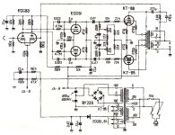
OP secondary:
I hope someone explains why the second winding is in parallel to half the first winding.
OP secondary:
I hope someone explains why the second winding is in parallel to half the first winding.
I also wolud like to understand, maybe somebody has information about this............
These Output transformers are partrigde parts?
These Output transformers are partrigde parts?
Nice thanks!
Ja ich spreche Deutsch...................
On my transformers there is no labeling like on japanese side shown............Is the sequnze of 0 4 8 0 16 ever the same ?
Ja ich spreche Deutsch...................
On my transformers there is no labeling like on japanese side shown............Is the sequnze of 0 4 8 0 16 ever the same ?
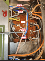
With handheld DVM you can identify the secondary coil parts.
0 is tied to the GND;
8 and 16 to the output hot;
4 and GND16 to the NFB part.
0 is tied to the GND;
8 and 16 to the output hot;
4 and GND16 to the NFB part.
That is a very confusing schematic. I think the two output windings are actually 0-4-8 (but labelled upside down) and 0-4 (not 0-16). When you connect the the 2 0-4 windings in series (no connection to the 8 ohm tap) you get 16 ohms as impendance goes with the square of the turns. When you connect the 2 0-4 ohm windings in parallel you get 4 ohms, with the option to get 8 ohms from the 8 ohm tap.
So if you label the schematic outputs from 1 to 5, bottom to top:
16 ohms - connect 2 to earth, connect 3 to 4, connect 5 to speaker out
8 ohms - connect 1 to earth, connect 2 to 4, connect 3 to 5, connect 3 and 5 to speaker out (as drawn)
4 ohms - connect 2 to earth, connect 2 to 4, connect 3 to 5, connect 3 and 5 to speaker out.
But I could be completely wrong...
Only with the beeper.ok, you mean the impedance or the inductivty?
See this.With handheld DVM you can identify the secondary coil parts.
0 is tied to the GND;
8 and 16 to the output hot;
4 and GND16 to the NFB part.

Good morning together, now i get realy confussed, the wiring diagramm in #13 is completley something different as shown in #2....or as shown on japanese side................
Or am I wrong ?
Or am I wrong ?
Is this correct -> This fits the japanese side:
Attachments
Last edited:
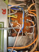
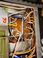
Firstly I think the diagram in post 13 (and hence my sketch) is wrong. I think the japanese transformer is different from yours (opposite). Yours is like the one on the german site. It seems earth is on the top right (can you confirm?), so top to bottom is 0 4 8 0 16. To change to 4 ohm you would connect the top two terminals together ("0" and "4") and connect the feedback wire (the pink wire??) to the speaker out ("8" and "16" which are connected together). But I'm not 100% sure.
"can you confirm?"
As I wrote, DVM beeper function helps identifying which is GND, which is "8R" output, which is gNFB.
As I wrote, DVM beeper function helps identifying which is GND, which is "8R" output, which is gNFB.
sorry at moment I cant make these check at my own , the amp is at maintenence and I try to check out how the situation is with the Outputtransormer...
But I will contact my technican that he makes some pictures and these mesurement you suggested......
But I will contact my technican that he makes some pictures and these mesurement you suggested......
- Home
- Amplifiers
- Tubes / Valves
- Michelson & Austin TVA-1 how to Change Output transformer from 8 to 4ohm