RF and RG in parallel give about 189ohms .. I put 180 as a standard value. Apart grounding any DC as talked about it earlier his is all about limiting input bias current for near ideal conditions, am I right?
OK...
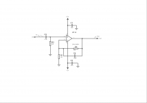
In your diagram R2 sets the input impedance. That means that any source component (microphone/cdplayer etc) sees that 180 ohm as a load across its output. 180 is extremely low.
I'm no expert on mics but there are two common types. Electret condensor ones which actually incorporate a FET transistor buffer and Dynamic mics which are just like a speaker or headphone driver but operated in reverse.
I think somewhere round about 1K ? is a typical value for an input resistor for a dynamic mic preamp and for a FET mic I would say more like 10k or higher.
Thats something you need to look into and specify what type of mic is going to be used.
----------------------------------------------------------------------------------------------------------
With a FET opamp such as yours there is no need to "balance" the input impedances as seen by the two opamp inputs because there is essentially zero current flow into and out of these terminals. Its in the pico and below amp range.
If it were an opamp such as the 5532 then it would be essential to balance these to minimise the DC offset shift caused by unequal input currents. For a bipolar opamp these could be in the micro amp range... many many times larger than the FET one.
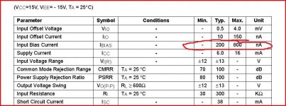
Look at this from a 5532.
Worst case and the input bias current is 800nA.
That means that 800nA could flow in the input pin connection. Imagine if R2 in your circuit above were 100K.
Using ohms law that 800na will develop 800e-9 *100e3 which is 0.08 volts. Nearly a tenth of a volt. If R1 in your circuit were left at 200 ohms then 800na would develop only 0.00016 volts.
So we have approx 80 mv imbalance at the input of the amplifier. That means that in order to bring the difference at the inputs back to zero the amplifier output must settle to a high DC voltage (an output offset voltage). That voltage of course depends on the feedback factor... the ratio... of the feedback network.
The FET opamp eliminates this problem entirely as there is no DC current flowing in the input pins to cause this offset voltage.
Hope that makes sense.
Attachments
OK...
In your diagram R2 sets the input impedance. That means that any source component (microphone/cdplayer etc) sees that 180 ohm as a load across its output. 180 is extremely low.
I'm no expert on mics but there are two common types. Electret condensor ones which actually incorporate a FET transistor buffer and Dynamic mics which are just like a speaker or headphone driver but operated in reverse.
I think somewhere round about 1K ? is a typical value for an input resistor for a dynamic mic preamp and for a FET mic I would say more like 10k or higher.
Thats something you need to look into
From my reading, most dynamic mics have an output impedance of 300-600ohm. It is generally recommended for the mic pre input impedance to be 5-6 times that. But, generally there is no issue with more and higher allows more usability with condenser mics. Higher also makes it easier to get lower bass cutoff with more reasonable input caps. At 180 ohm, I think you may be missing your assignment criteria, without going back to look at it.
Thanks all of you especially mooly for the help and good info! I learned a lot from this assignment. Today I just handed it in and my lecturer was very happy.
I personally own a TAS475 in a very good condition and this summer i would like to experiment with some high end op amps, in fact I order the opa243 from a local distributer online. it cost about €5. The thing is that this scope needs some calibration. To tell you the truth, I managed to get hold of the oroginal reference manual. There are lots of calibration types like; display driver, factory horizontal cal, factory vertical cal, low freq output compensation, high frequency step response, attenuator compensation and vertical gain adjustment.
The majority of the calibrations require a one time mark generator, one pulse generator and DC calibration generator.
I tried to find some people I know that can help me out but when I took it to their workshop they just connect it to a power supply and told me that it is giving correct reading but I read my manual and I am not satisfied. I want to do the calibrations myself.
Which of these calibrations are not that critical? And when mentioning the apparatus needed is it a must to use very high precision signal generators etc?
If you think the above post should be a new thread go ahead, I started it here because I like to be guided by the same friendly people 😉
If you want folk to see it then it should be in a new thread really 🙂
Just very quickly... we can elaborate more on the details... a variable DC source which can be just a pot and resistors and a high enough voltage battery/s is good for calibrating the vertical amplifier and checking the attenuator.
The vertical amp is normally calibrated on the most sensitive setting (but no active gain switches turned on such as x5 etc). The most sensitive setting is normally "straight" from input to vertical amp. So get that right using a DVM and variable supply such that the trace deflects by the correct amount, say 5 squares for 5 millivolts applied if the setting is 1mv /div. Then check the switched attenuator by working up as high as you can... errors here though are rare.
For the horizontal timebase stray mains pickup at 50/60 hz is a good reference. Even better build a simple cystal oscillator (cmos or ttl) and feed a decade counter/s to divide it down. If you google scope calibrators there must be loads of designs...
A fast risetime square wave is good for checking any frequency compensation on the attenuator but again, these should be perfect unless they have been twiddled.
That's it very briefly... if you want to know more then ask and we can go through it step by step.
If you use a pot make sure the DVM is always attached as it will load and alter the voltage a tiny bit if the pot/resistors are high value... so always have the reading on the DVM while you adjust the scope.
And remember for AC voltages a DVM displays an RMS voltage... scope has to be calibrated for peak voltages.
- Status
- Not open for further replies.
- Home
- Source & Line
- Analog Line Level
- Mic pre amp Problem