Hi folks,
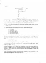
I need some help in the mic amplifier where I have to find a suitable op amp. My specs are an input of max amplitude of 150mV from mic and an output of 3v max amplitude from op amp. The output bandwidth from microphone is stated to be from 200Hz to 20kHz. The op amp will be supplied from +12V and -12V (dual supply). I have a good idea on parameter i have to consider like bandwidth, slew rate etc in fact I decided to work with OPA2134.
There were some hints in class regarding the addition of rc filters but the thing is that in the problem it doesn't specify any dc offset in the input and so I can see the need for a coupling capacitor at the input. And when it comes to low pass do you think there is a need?
the problem is attached.
thanks a lot
Attachments
Since this is clearly a homework assignment, and you clearly wouldn't want to cheat by passing off others' answers as your own, let's just ask a few questions. First: Given the max input voltage and the max output voltage, what does the gain need to be?
If we decide to put R2 = 2k , then Rf would be 38k.. we'll use 36k for a standard value which will give a gain of 19 which is quite close.. what do you think?
Yes first I thought of creating a voltage divider (two 47K) from +12V vcc to -12V vcc for the input to swing on 0v and have plenty of headroom..
Nothing wrong... ratio is fine and gives a voltage gain of 19
Why use two 47k (or any other value)... think 🙂
Why use two 47k (or any other value)... think 🙂
We need a high input impedance not to load the signal source.. the dc supplies being ac ground.. (47k//47k)that is our main function of using an opamp... (the input impedance of the op amp alone is assumed to be infinite 🙂
So what DC voltage does the input (non inverting input) need to be biased to in this design...
Using one component is all you need to do this and define the input impedance.
Using two resistors as you say would work but also has two significant drawbacks.
Using one component is all you need to do this and define the input impedance.
Using two resistors as you say would work but also has two significant drawbacks.
Sorry for creating confusion. For some reason the relevant posts did not appear here at first - some sort of cacheing problem, blown off course over the north atlantic?? Now they have appeared, nearly two hours later!
to add a coupling capacitor I think... this will block the DC if there is some dc offset..
Remember the basic rules of opamp design that cover 99.9% of applications.
"For an opamp with feedback, the output will do whatever is necessary to keep the difference between the two inputs at zero volts.
So for the output to sit at zero volts DC (which is what you want), the input also has to be at zero. It also can not be left floating.
So a single resistor (the value of which determines the input impedance) is required, and that is connected from the non inverting input to "ground" which is your zero (0 volts) point.
Can you see any reason now why two equal value resistors (as you mentioned) would have worked but would not have been ideal.
An input coupling capacitor would also be advisable... can you see why ? and under what conditions its needed.
Just wanted to say I am finding this tread really helpful. Thanks for the questions and the answers!
With the voltage divider I would have a dc of VCC/2 at the input. The coupling capacitor would block this dc.
- Status
- Not open for further replies.
- Home
- Source & Line
- Analog Line Level
- Mic pre amp Problem