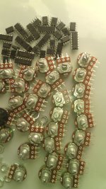
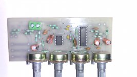
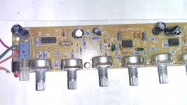
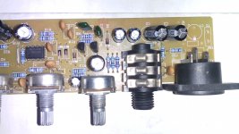
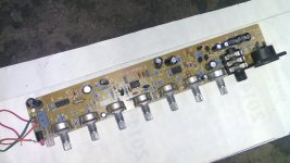
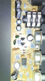
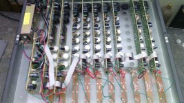
this is professional mixer sound quality good but ml3 is best.but this mixer have aux send return function and clip and mute function.
Attachments
Last edited:
hi,
i anybody has pcb for 35v-0-35v to drive amp along with 15-0-15 v to drive tone controls ?
regards
prasi
i anybody has pcb for 35v-0-35v to drive amp along with 15-0-15 v to drive tone controls ?
regards
prasi
Ideea
.jpg") Sorry, I'm not familiarized with pcb software, you should try like 2Kohm 2W and 1.3W zenner
Sorry, I'm not familiarized with pcb software, you should try like 2Kohm 2W and 1.3W zenner
Also, diode brigde have usually the + terminal not in the corner, you should add some fuses on +/- power rails and 100 nF ceramic caps close to DC power connector and some 100uF electrolitics on +/-15
Sorry, I'm not familiarized with pcb software, you should try like 2Kohm 2W and 1.3W zennerAlso, diode brigde have usually the + terminal not in the corner, you should add some fuses on +/- power rails and 100 nF ceramic caps close to DC power connector and some 100uF electrolitics on +/-15
Last edited:
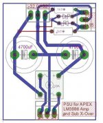
it is not good using same transformer for preamp or crossover and amp there should be another secondary winding for it 12-0-12.you will get heat problem and didn't get good current for crossover.it may be wok but not you got quality and reliable.
HI rohin,
thanks for the reply. I am planning on using the above PS in a sub powered by APEX LM 3886 amplifier and sub x-over circuit given in this thread by APEX.
I have a transformer that has 24-0-24 (5 amps) and 12-0-12 (500mA). Do you have any PSU circuit that is suitable to drive the above combination?
regards
prasi
you can use four 4007 diode and then add two cap and use 7815 and 7915 for crossover but you can not use this circuit from dc voltage like +-32.you should use 12-0-12 ac source.if there is doubt in mind i will clear for you.HI rohin,
thanks for the reply. I am planning on using the above PS in a sub powered by APEX LM 3886 amplifier and sub x-over circuit given in this thread by APEX.
I have a transformer that has 24-0-24 (5 amps) and 12-0-12 (500mA). Do you have any PSU circuit that is suitable to drive the above combination?
regards
prasi
HI, ROhin,
Thanks for the reply. I will try to find a PCB that has both 12-0-12 AC i/p (for xover ) and 24-0-24 AC i/p for amplifier.
reg
prasi
Thanks for the reply. I will try to find a PCB that has both 12-0-12 AC i/p (for xover ) and 24-0-24 AC i/p for amplifier.
reg
prasi
no,don't joint the both ground it is not good sometime.it will joint automatic when you give signal to amp through crossover.
Last edited:
Schematic Help - Pieze/Condenser Mic switch
Hi. I've been doing some dabbling into a preamp for my upright bass. So far, I've got it going using a piezo, but wondered if anyone could look at my schematic and hopefully tell me how i could modify it slightly in order to use a condenser mic with phantom power, activated by switch. I'm planning on using an XLR input in which the extra pin (2 or 3? *not shown on schematic) will be either grounded or floating when using a piezo, or used for phantom power in case of a mic. I'm looking for what components would be needed between input pin to opAmp and which opAmp pin those would continue to. Any suggestions or direction would be appreciated.
Hi. I've been doing some dabbling into a preamp for my upright bass. So far, I've got it going using a piezo, but wondered if anyone could look at my schematic and hopefully tell me how i could modify it slightly in order to use a condenser mic with phantom power, activated by switch. I'm planning on using an XLR input in which the extra pin (2 or 3? *not shown on schematic) will be either grounded or floating when using a piezo, or used for phantom power in case of a mic. I'm looking for what components would be needed between input pin to opAmp and which opAmp pin those would continue to. Any suggestions or direction would be appreciated.
An externally hosted image should be here but it was not working when we last tested it.
PIN 1 is chassis.
Pin 2 is Hot Input
Pin 3 is Cold Input.
For balanced connections this is the normal way to wire up the XLR.
For unbalanced connections, Pin 3 becomes the Signal Return.
No changes to the interconnects, no changes to the Source, no changes to the Receiver.
Remember that a Source sends out a DIFFERENCE between Hot and Cold.
A Receiver measures that DIFFERENCE signal and scales it, to present to it's output.
- Home
- Live Sound
- PA Systems
- Mic, Line, EQ... Preamps