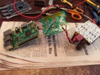
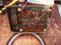
Mezzanine board designed to remove mesh of wires and feed both PI and DAC independently from single board using standard GPIO, Module B feeds Raspberry PI and Module C1 (or C1+C2) feeds DAC module, Module A used as pre regulator
6VDC/2A power source required to feed Mezzanine. (actually 1 A is enough in most cases, if you don't connect external USB loads)
6VDC/2A power source required to feed Mezzanine. (actually 1 A is enough in most cases, if you don't connect external USB loads)
Mezzanine board designed to remove mesh of wires and feed both PI and DAC independently from single board using standard GPIO, Module B feeds Raspberry PI and Module C1 (or C1+C2) feeds DAC module, Module A used as pre regulator
6VDC/2A power source required to feed Mezzanine. (actually 1 A is enough in most cases, if you don't connect external USB loads)
Module A must always be included?
Is it true when I connect LDOs in series (for example module A and module C) then total PSRR is sum of PSRR module A and PSRR module B?
My case:
I have smps which operates on 100KHz. PSRR at 100KHz of module A (LT3086) is 30db and PSRR of module B (LT3045) 78db. Is total PSRR 108db for my case?
My case:
I have smps which operates on 100KHz. PSRR at 100KHz of module A (LT3086) is 30db and PSRR of module B (LT3045) 78db. Is total PSRR 108db for my case?
I've been running an RPi source off of a Pi modified with this board to replace the on-board DC-DC switching converters for the last 3-4 weeks. NICE!
IF you want the absolute best SQ you can get out of an RPi sourced setup (at least in my experience... and I've tried a LOT of things), you need to do this to a Pi and listen.
I commented on the various power options I've tried with RPis in this post:
ES9018K2M, ES9028Q2M, 9038Q2M DSD/I2S DAC HATs for Raspberry Pi
Attachments
I purchased one from website ... seems to be held up at postoffice in Cincinnati for an unusually long time ... my tracking says it arrived in NYC 7/1, made it to Cincinnati regional 7/6 ... and then "in transit to next facility" ... are they trying to figure out what it does or should I just be patient?
In the beginning of this year, I had a package from Alexey that got stuck in receiving customs in NY. After a few weeks, I contacted him. He said he'd seen that happen occasionally and most of the time they'd start moving again within a month.
That one stayed stuck over a month and he ended up declaring it dead, filing a claim, and sending a new shipment.
Check with Alexey on options if you haven't already.
I hope you get it soon!
Greg in Mississippi
That one stayed stuck over a month and he ended up declaring it dead, filing a claim, and sending a new shipment.
Check with Alexey on options if you haven't already.
I hope you get it soon!
Greg in Mississippi
In the beginning of this year, I had a package from Alexey that got stuck in receiving customs in NY. After a few weeks, I contacted him. He said he'd seen that happen occasionally and most of the time they'd start moving again within a month.
That one stayed stuck over a month and he ended up declaring it dead, filing a claim, and sending a new shipment.
Check with Alexey on options if you haven't already.
I hope you get it soon!
Greg in Mississippi
This story bit different, it is released by NY
and
July 6, 2018, 8:55 am
Arrived at USPS Regional Facility
CINCINNATI OH NETWORK DISTRIBUTION CENTER
July 7, 2018, 7:48 am
Departed USPS Regional Facility
CINCINNATI OH DISTRIBUTION CENTER
July 10, 2018
In Transit to Next Facility
The item is currently in transit to the next facility as of July 10, 2018.
I can not claim if transit time less than 30 days. Best option if you can contact nearest USPS office to check current status.
I worst case i will resend
I've been running an RPi source off of a Pi modified with this board to replace the on-board DC-DC switching converters for the last 3-4 weeks. NICE!
IF you want the absolute best SQ you can get out of an RPi sourced setup (at least in my experience... and I've tried a LOT of things), you need to do this to a Pi and listen.
I commented on the various power options I've tried with RPis in this post:
ES9018K2M, ES9028Q2M, 9038Q2M DSD/I2S DAC HATs for Raspberry Pi
Did you disable the DC/DC convertor or RPI ? I assume you just removed the IC..or a compoenent around it. Did you test the RPI power requirements at 3.3V and 1.8V (ma) ?
Ioan,
I just removed the IC. I haven't gotten the datasheet, I suspect one could disable it too by cutting a lead... but then the rails would be driving the inputs/outputs of the chip.
It is not an easy chip to remove, as it has a large heatsink base. The first couple of times I did it I used a combination of hot air from my rework station and a large soldering iron applied to the top of the chip. The last time I crushed as much of the package as I could remove with pliers and then used the hot-air/large iron combo.
Also the first time I did one, I soldered the leads from the regulator outputs to the output end of the appropriate output capacitors of the DC/DC converter, which I left in place. The 2nd time I soldered the leads to the appropriate test point pads on the bottom of the board which made for a cleaner and more direct connection, but to make sure the leads wouldn't pull the pads, I also used hot-glue to secure the wires and strain relief the build.
I'll post the pictures I used as guides or links to them in other threads later today or this weekend.
Greg in Mississippi
I was checking the RPi3B+ and it seems that it has more power rails than RPI3B..
RPI3B+ connection is different..
RPI3B+ connection is different..
This story bit different, it is released by NY
and
July 6, 2018, 8:55 am
Arrived at USPS Regional Facility
CINCINNATI OH NETWORK DISTRIBUTION CENTER
July 7, 2018, 7:48 am
Departed USPS Regional Facility
CINCINNATI OH DISTRIBUTION CENTER
July 10, 2018
In Transit to Next Facility
The item is currently in transit to the next facility as of July 10, 2018.
I can not claim if transit time less than 30 days. Best option if you can contact nearest USPS office to check current status.
I worst case i will resend
Yeah really weird ...

I was checking the RPi3B+ and it seems that it has more power rails than RPI3B..
RPI3B+ connection is different..
Yep, was considering removing the DC/DC chip but it also outputs 1.2V 😱
On the other hand RPi 3 B+ has 802.11ac so makes a killer streamer (doing DSD256 upsampling using HQPlayer ... some dropouts with DSD512)
Last edited:
On the other hand RPi 3 B+ has 802.11ac so makes a killer streamer (doing DSD256 upsampling using HQPlayer ... some dropouts with DSD512)
With which DAC do you get this?
Thanks
Matt
Would it be possible to feed the Mezzanine board with only modules C, D and E populated by LT 3045 from 7V DC out of a battery? The website says "Input Voltage Range : 6VDC" – so 7V might kill the board?
Hi
6V limitation only if Module B fed directly from PSU
If Module A installed, or only C1/2,D,E (without ModuleB) - can feed with 7VDC
Alex
6V limitation only if Module B fed directly from PSU
If Module A installed, or only C1/2,D,E (without ModuleB) - can feed with 7VDC
Alex
Parts List
Hi,
anyone could provide a parts list to populate the board.
I ordered only the pcb. So I would need the parts list.
Thx
Branko
Hi,
anyone could provide a parts list to populate the board.
I ordered only the pcb. So I would need the parts list.
Thx
Branko
Hi,
anyone could provide a parts list to populate the board.
I ordered only the pcb. So I would need the parts list.
Thx
Branko
Have you contacted the manufacturer? - www.ldovr.com - Impex Technology FZE P.O. Box 38271, R.A.K., U.A.E. +9717 2077556 alexey.dxb@gmail.com
Thanks to oxothuk, my boards arrived today. This looks like a very elegant solution - thank you!
Now...I would like to get this baby plugged into my pi 3B+. I'd like to replace the onboard 5v, 3.3v and 1.8v with the mezzanine board but I obviously want to leave the 1.2v supply intact - so it sounds like removing the dc/dc converter is a no-no? I'm assuming that I might just be able to lift the appropriate output leg of the chip and then replace it with the new supply?? Can anyone point me to a resource that shows me the best points to inject the 3.3 and the 1.8v? From the posts above I couldn't discerne whether the 3.3v would be supplied via the GPIO or I'd need to solder onto the pi tracks/component somewhere.
Cheers,
Crom
- Home
- Source & Line
- PC Based
- Mezzanine Power board for Raspberry Pi