Salas,
I am considering using the FE of the MEsmerize to accept balanced inputs. Would you be willing to post the layout so that I can see if I can effectively split the input relays to go from 6 Se inputs to 2 balanced and 2 unbalanced.
I am considering using the FE of the MEsmerize to accept balanced inputs. Would you be willing to post the layout so that I can see if I can effectively split the input relays to go from 6 Se inputs to 2 balanced and 2 unbalanced.

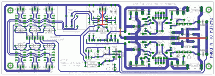
Its posted before, but here it is again, the threads are too long to hunt it.
I figured you probably had, but as you say, too long. THanks.
System of a Down. No wonder you guys are having trouble over there😀
Last edited:
 Its always our fault.
Happy new year with health, good job and enjoyment to everybody.
I need your lights about C8. Can I use 120uf (which I have on hand) instead of 100 ?
I understand that R24/C8 form the start up time delay and for this I'm nearly sure that 120uf is not a problem. I'm not sure how such a change affects "power off".
I need your lights about C8. Can I use 120uf (which I have on hand) instead of 100 ?
I understand that R24/C8 form the start up time delay and for this I'm nearly sure that 120uf is not a problem. I'm not sure how such a change affects "power off".
Thanks. The 50k pot was no good in my jfet boz too. 🙁
FWIW, Borberly gives a good explanation of why this is the case in his articles, Jfet Frontiers.
Happy new year with health, good job and enjoyment to everybody.
I need your lights about C8. Can I use 120uf (which I have on hand) instead of 100 ?
I understand that R24/C8 form the start up time delay and for this I'm nearly sure that 120uf is not a problem. I'm not sure how such a change affects "power off".
No worries. Keep in mind, a 100uf is normally +/- 20% value anyways.
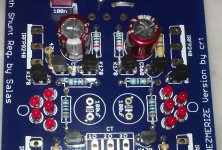
Since photos are never useless in a construction thread let me show you how I implemented the C1/C3 mod.
I left the the pcb holes unused (photo). I left the leads of the 1st and last led leads uncut. I wedged in between these leads the plastic capacitor leads and soldered.
Capacitors are 0,33 uF 250V NOS Siemens MKP.
I left the the pcb holes unused (photo). I left the leads of the 1st and last led leads uncut. I wedged in between these leads the plastic capacitor leads and soldered.
Capacitors are 0,33 uF 250V NOS Siemens MKP.
Attachments
Looks good. You had some OPA627 pre if I recall correctly? Not needing gain anymore, or the buffer goes to another system?
You remember always well !!!!!!
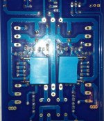
The 627 was a buffered 10K ALPS with a touch of gain on both IC's (x 1,5 I think) . Recently disassembled to take ALPS for Mezmerize 😀 (photo).
I was playing it with 2 12V 7Ah batteries. That was were our roads crossed ... I replaced batteries with your shunts with sparkling results. Aaaaa I recently saw your reference to my impressions in the MPP thread. The thread is too long and dense... Did they agree with my impressions ?
Attachments
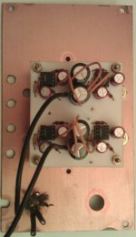
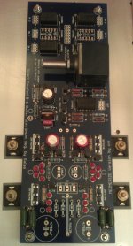
I have finished staffing and I have a question before starting tests.
I will reuse an existing psu off board. On board bridge will be omitted but I would like to use the existing pads for local decoupling. What's the minimum capacitance you would advice me to use ?
I will reuse an existing psu off board. On board bridge will be omitted but I would like to use the existing pads for local decoupling. What's the minimum capacitance you would advice me to use ?
Attachments
- Home
- Amplifiers
- Pass Labs
- Mezmerize DCB1 Building Thread