Salas, in post 1669 you wrote:When there is a problem with sourcing good semis you may test an alternative I just thought for you regarding the Mez PSU section. Use Fairchild PF5102 (currently in production) for all the JFETs except those two next to the 10R resistors places. You omit those two JFETs. You jumper their outer pads instead with short wires and you use 120R instead of 10R next to them. The resistors value change is mandatory, not something to be left for later. 100R is acceptable too. Don't try other random values. See attachment.
Now I have got genuine 2SK170BL from France.The alternative in the power section you decribe and the picture you attache was ment for PF5102 in the power part of Mezmerize.Will it be ok to use 2SK170BL as shown in the attachement (changing 10 oms to 120 ohm and use the two jumpers)? If I can do this, I can "save" two
2SK170 BL per PCB. I do need 2SK170BL for some future NP F5 builds.
Another question: I am a little unsure about the 2x68R resistors in the power section. Has it somethings to do about the use of 6 or 12 V relais?
Eivind S
Yes you can do the alternative when using original rest of PSU JFETs too if you got a good parts economy reason to do the alternative. It also makes the two 5 leds voltage references running predictable & same own current not by need of matching rare JFETS at this spot for the ease of mind of the perfectionist.
The 2x68R is for running low CCS current. Some used to not have space for sinks as they wanted to integrate with a power amp etc. Some put three 68R for bit more current and small clip on sinks, most build it with a single 10 Ohm 2-5W there instead, and bolting the MOSFETs to the chassis for about 150-200mA setting. The exact amount is not always the same due to MOSFETS LEDS JFETS tolerances.
The 2x68R is for running low CCS current. Some used to not have space for sinks as they wanted to integrate with a power amp etc. Some put three 68R for bit more current and small clip on sinks, most build it with a single 10 Ohm 2-5W there instead, and bolting the MOSFETs to the chassis for about 150-200mA setting. The exact amount is not always the same due to MOSFETS LEDS JFETS tolerances.
Welcome to the forums. Make sure that the 10 Ohm resistor on (+) side is 10 Ohm indeed first and not higher by mistake. Change the FET next to that 10 Ohm resistor if she is right.
Yes, this helped. Replaced the FET and everything works now. Thanks!
You don't need to match the LEDs
They each just drop some voltage and the string of LEDs drops a bigger voltage.
What voltages do you have at the AC input and at the DC input?
Yes, right, it was not the LED's matching. They all showed around 1.66V each when working with that (sub par?) FET. After replacing the FET everything went on properly. Thanks everyone
OK, success. Some dud JFET. Let us know how you liked it too.
Very nice. Pre amp is not the weakest link in my current system, so I was not expecting a huge difference in overall performance. I was positively surprised I have to say
That's positive, it offered something too when wasn't built for targeting a specific weakness. It has to open up somewhat more with play, the lytics will flex. What was in its place before?
Pretty much nothing 🙂 Recently just DAC feeding the Quad405 clone fitted with volume control. This amp needs at least some rewiring for sanity. Or, what is more likely, a replacementWhat was in its place before?
Dcb1 usually goes nicely with DACs. They are high output already so its being a minimal circuitry buffer as system controller does not detract much.
DCB1 Blues
Hi
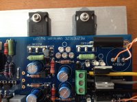
I've been hoping to sort this out myself, but frankly I'm stumped. Ten 2sk170 are used, all other parts meet the DIYstore's BOM specifications. On initial power up no LEDs lit. One of the large 10 ohm resistors got (too) hot, the other stayed cool. I changed out a bad mosfet and powered up again. This time both of the big 10 ohm resistors got hot fast; I killed the power before damaging anything (I hope).
Long legs on the LEDs went to the square pad. I've got something backwards, but what? Hope you guys can put me on the right path.
Keith
Hi
I've been hoping to sort this out myself, but frankly I'm stumped. Ten 2sk170 are used, all other parts meet the DIYstore's BOM specifications. On initial power up no LEDs lit. One of the large 10 ohm resistors got (too) hot, the other stayed cool. I changed out a bad mosfet and powered up again. This time both of the big 10 ohm resistors got hot fast; I killed the power before damaging anything (I hope).
Long legs on the LEDs went to the square pad. I've got something backwards, but what? Hope you guys can put me on the right path.
Keith
Attachments

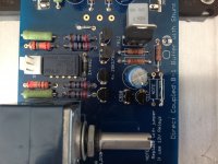

Follow the D shape symbol on the PCB next to each bunch of LEDS to debug orientations. Only that shape as key because on this board there is no pad shape convention. Flat D side is (-). I believe you will find them installed backwards. Also check them twice for health with 9V battery quickly before and after properly oriented/soldered back because 3mm LEDS are sensitive to longish heat application and rework. Or with a DMM in diode mode that you know it puts out enough voltage to light up such an LED. Check the DMM diode mode with an unused one first. So to spot and replace any possibly dead ones too before the new power up attempt. Also avoid extension wires for those nice expensive electrolytics in the final build. If you must use them employ bits of thick copper wire to just clear the height of the nearby components by extending those capacitors short legs. Finally make sure that the two back to back bridge diodes don't short. Pull them a bit apart or put a Silpad in-between.

Long legs on the LEDs went to the square pad. I've got something backwards
Yes, the LED's.
Also make sure the middle two rectifier diode tabs don't touch each other, they are usually connected to the cathode; to prevent accidental shorting, use an insulator between the tabs and secure using a nylon nut and bolt.
You beat me to it Salas 😀
Attachments

Last edited:
I have one batch of LEDs that has the big reflector bowl on the other side. Prior to receiving these oddballs, I had thought that the big reflector bowl could ONLY be on the negative side. But there are exceptions waiting to trick us!
615498
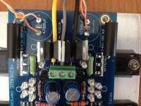
Your mains wiring is too dangerous. Exposed 110/120Vac very close to your work area. !!!!
Your mains wiring is too dangerous. Exposed 110/120Vac very close to your work area. !!!!
Tricks indeed. These particular LEDs don't have have a flat side so I didn't reference the D symbol...and assumed the anode went to the square pad...wrong. Thanks for the tip about insulating the rectifier diode backs.
I'll try and get this sorted on the weekend and let you know how things work out. Thanks again.
Keith
I'll try and get this sorted on the weekend and let you know how things work out. Thanks again.
Keith
I usually just put the diode into my DVM. When it lights up, I am sure which lead is positive 🙂
I usually just put the diode into my DVM. When it lights up, I am sure which lead is positive 🙂
Good advice Albert; in the end this is what I did.
All is good, I have lights and action. I'll check board voltages, put it all in a case, and park it between my tubed phono pre and EL34 power amp. Hoping for good things.
Thanks everyone for the excellent drawings and advice.
Keith
Nice to know it works. Keep us posted about your results in the system and snap a photo or two when ready if you may.
OK, I checked some voltages and something isn’t right.
AC:
+14.08V
-14.08V
Mid board test points
+9.66V
-9.65V
Triplex LED’s
+5.54V
-5.72V
Quintet LED’s
+9.15V
-9.30V
DC Offset
Don’t seem to be getting anything.
Voltage across the output diode is a couple of millivolts.
It seems at one point I measured 17+ V on the output leg of the regulator but now see 10.6V.
Could I have toasted it with an ill-fitting sink, since removed?
Attachments

- Home
- Amplifiers
- Pass Labs
- Mezmerize DCB1 Building Thread