I figured a ~$35 potentiometer would be great but I was disappointed. The PEC construction is good and it will last a long time but the precision is missing. I used a 1kHz signal and recorded the rms voltage on a dual channel scope as I swept it ~5 degrees at a time - not a good result. I'm not sure how much imbalance is objectionable but I would think that ~0.5 dB should be a goal.
With steppers its no problem but good track pots maybe able not to overshoot 1dB at their worse points. Comes down to individual samples too.
That's a good point and I think the TKD is actually a stepper if I read the notes correctly, the conductive plastic has discrete steps that are laser trimmed.
Great info on Potentiometers.
Can there be L/R crosstalk in stereo pots? Real Cheapies?
Can there be L/R crosstalk in stereo pots? Real Cheapies?
Last edited:
Can there be L/R crosstalk in stereo pots? Real Cheapies?
I think so but I haven't measured it personally, it's probably low <60 dB. What I think is more of an issue is channel imbalance on a stereo (or more gang) potentiometer. Digital volume controls have made this less of an issue but they have their own deficiencies.
That's a good point and I think the TKD is actually a stepper if I read the notes correctly, the conductive plastic has discrete steps that are laser trimmed.
Kinda ladder configured in its own way but it has a wiper not a switch
Kinda ladder configured in its own way but it has a wiper not a switch
I see what you are saying - if I understand correctly the wiper rides along a resistance track that also has discrete resistances connected in a ladder fashion to achieve the overall resistance?
Yes its like a ladder but with one side continuous track. A ladder switch would have another set of vertically shown discrete resistances and a contact moving between them, connecting one opposite pair at their noses then going to the next pair etc.
The TKD should be here by the end of the week and I will measure it throughout the throw and report back - I'm hoping it's good but I will give the results as they are.
The TKD should be here by the end of the week and I will measure it throughout the throw and report back - I'm hoping it's good but I will give the results as they are.
Yep, let us know.
sound warmth
Hi. 2sk209gr is interesting part.It has about 10dB more H2 but has less H3 than 2sk170bl.Maybe it sounds better than 2sk170 because of more H2 adds warmth to sound and H3 is lower so sound may be nicer? Anyone compared them and could tell about sound? I have reel of 3000pcs of 2sk209gr.Did not have a spare time to play with them yet but i want to try them a lot
Hi. 2sk209gr is interesting part.It has about 10dB more H2 but has less H3 than 2sk170bl.Maybe it sounds better than 2sk170 because of more H2 adds warmth to sound and H3 is lower so sound may be nicer? Anyone compared them and could tell about sound? I have reel of 3000pcs of 2sk209gr.Did not have a spare time to play with them yet but i want to try them a lot
Attachments
There is significant IDSS difference between BL and GR so transconductance was even more different than only due to type differences for those JFETs in the table. When using two 2SK209GR in parallel to truly replace a 2SK170BL the combo's transcoductance and Ciss come up comparable. I don't know if they would keep the same THD profile characteristics of that test then. If the 2SK209GR THD profile was due to secondary things in its production process, not just because of IDSS, Gm, Ciss, that profile may stay. Its a preferable profile anyway.
Hi.Patrick wrote these
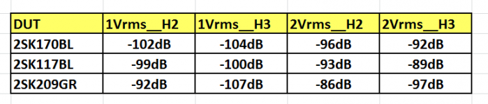
The JFETs tested were
a. 2SK170BL at 8.2mA Idss
b. 2SK117BL at 7.5mA Idss
c. 2SK209GR at 3.8mA Idss
Single-ended input signal was 1Vrms and 2Vrms at 1kHz from the AP built-in waveform generator.
The results can be summarised.
DUT 1Vrms __H2 __H3__ 2Vrms H2 __H3
2SK170BL -102dB -104dB -96dB -92dB
2SK117BL -99dB -100dB -93dB -89dB
2SK209GR -92dB -107dB -86dB -97dB
As can be seen, there is very little performance difference between 2SK170 and 2SK117 (= 2SK209 in SMD) at the same Idss; on average about 3dB.
Halving the Idss push up the second harmonics by so 6dB, in return for 7dB lower third harmonics. The latter result (with the low H3) was rather unexpected and interesting.
It is here
NJFETs for Source Follower Applications
-----------------------------------------------------------------------------------
I want to use them instead of 2sk170bl but i could not find a suitable adapter which can be put over eachother instead of near eachother(there are double sided sot23 adapters everywhere on ebay and aliexpress ).Maybe we can make pcbs for them and put cooler on them.
I want something like this but parallel to eachother and narrower one.Also want much cheaper
SOT23-3-X2-DIL
Last edited:
Its a practical thing to solve as elegantly as someone chooses but a readily easy approach that comes to mind, at least for a test, is use classic single SOT-23 adapters and solder one on top and one under the DCB1's PCB for each through hole 2SK170BL places in the quad. The PSU related places can be GR singles, no problem. The LEDS still bias alright with GR.
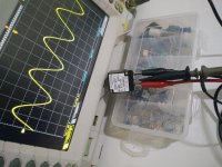
TKD potentiometer
The TKD 20k potentiometer arrived today and I measured it at 10 degree intervals. Channel balance is good, ~0.3 dB or better in the typical use range.


The action on it is really smooth with just enough resistance, there doesn't seem to be any noticeable lash from the motor.
Yep, let us know.
The TKD 20k potentiometer arrived today and I measured it at 10 degree intervals. Channel balance is good, ~0.3 dB or better in the typical use range.
The action on it is really smooth with just enough resistance, there doesn't seem to be any noticeable lash from the motor.

Thanks Salas, the Mezmerize and 6-24 crossover PCB also showed up today so I need to get the rest of the parts and start building.
One difference I noticed between a TKD potentiometer and a Goldpoint stepped attenuator is the rotation life. The TKD specs 100,000 cycles minimum and the Goldpoint 25,000 minimum. I'm pretty sure neither will fail during the normal lifetime of a piece of audio equipment but it suprised me that the TKD spec was 4x the Goldpoint.
- Home
- Amplifiers
- Pass Labs
- Mezmerize DCB1 Building Thread