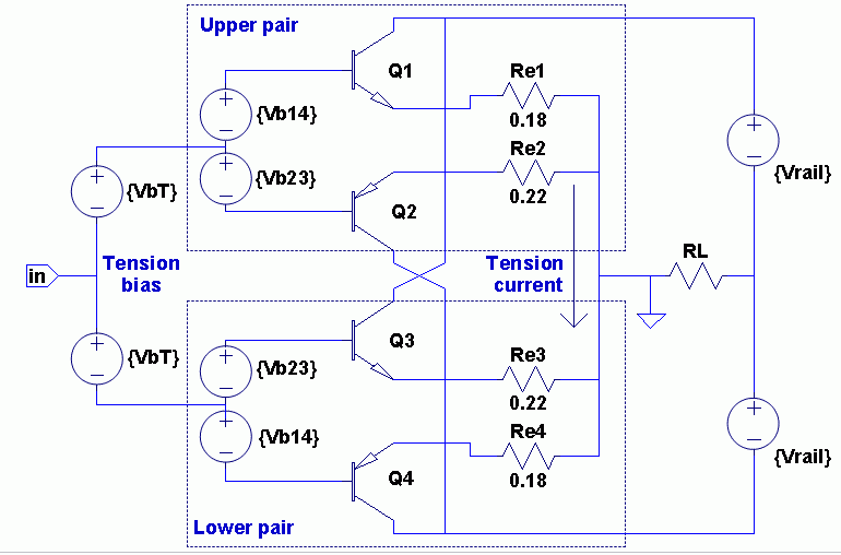
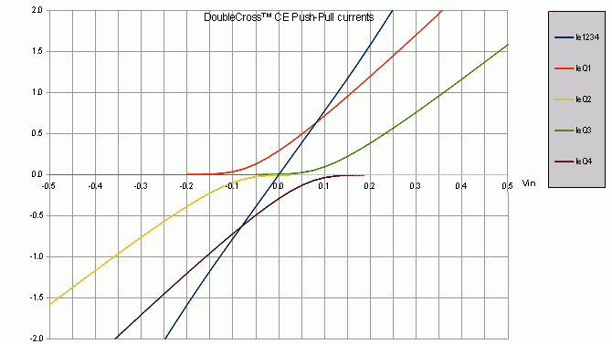
Also "Class-AB+C is the same thing as Bob Cordell's DoubleCrossTM" in this thread here Class AB+C: Anybody tried it? Is it worth it? with plots and circuit here and a copy below
Also see Bob Cordell's Power amplifier book
Also see Bob Cordell's Power amplifier book
Last edited:
Also "Class-AB+C is the same thing as Bob Cordell's DoubleCrossTM" in this thread here Class AB+C: Anybody tried it? Is it worth it? with plots and circuit here and a copy below
...
Also see Bob Cordell's Power amplifier book
That is a very good contribution to the research
To my knowledge there is no ultimate technique out there to perfectly linearize an output stage; hence, if you come up with one, you will be the hero. The best you can do is do the optimal bias which you already do and then work from there. Things you can do at this point are:
- Increase open loop gain over frequency: Two-pole compensation, higher cross-over frequency. Note that more DC gain will not help you.
- Use local feedback techniques: TMC or OITPC compensation schemes.
- Do error correction: There are a few techniques that sample the error across the output stage and then do something clever with it.
I have not studied Bob Double-Cross yet which looks promising, but from Ian's post, is not a panacea solution either.
Look at Mike Renardson improved class b amplifier it completely removes cross over distortion
The guy is a real genius but very modest re his work
Trev
The guy is a real genius but very modest re his work
Trev
Look at Mike Renardson improved class b amplifier it completely removes cross over distortion
The guy is a real genius but very modest re his work
Trev
Do you have a link?
Nope, doesn't remove crossover distortion - on a good day it may reduce it at low signal levels, I found at high signal levels it was less effective than a symmetrical arrangement. The circuit he shows has massive 1 ohm emitter resistors in a CFP triple output stage, just reducing those to 0.1 ohms has more significant effects.Look at Mike Renardson improved class b amplifier it completely removes cross over distortion
The guy is a real genius but very modest re his work
Trev
With a bit of fiddling its possible to get close to -90dB output stage distortion using 0.1 ohm and the Renardson circuit, but a standard CFP output can get to -85dB more consistently especially at high output.
The version using opamps is probably really good, but then there's plenty of gain available to linearize.
Dosn't this resemble Bryston designs?Also "Class-AB+C is the same thing as Bob Cordell's DoubleCrossTM" in this thread here Class AB+C: Anybody tried it? Is it worth it? with plots and circuit here and a copy below
Also see Bob Cordell's Power amplifier book
Best regards!
Also "Class-AB+C is the same thing as Bob Cordell's DoubleCrossTM" in this thread here Class AB+C: Anybody tried it? Is it worth it? with plots and circuit here and a copy below
Be good to have gull-wing graphs for this variation, its the most powerful way to visualize cross-over effects. A gull-wing graph plots voltage gain(*) against input voltage.
(*) which is usually centered around 0.96 for output stages - the vertical axis would typically be 0.9 to 1.0. Gull wing graphs are very characteristic of the output topology and tell you far more than a THD figure.
Common Collector version below

The LTspice file is attached.
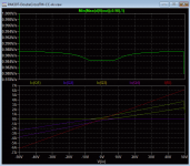
Distortion within the flat region is probably not audible given >90dB speakers and the flat region covers a few watts so it appears the majority of our listening range can be effectively crossover distortion free.
So global feedback is not need using this OPS. Maybe there should be posts in the Pass Labs area about this? Since it looks to me like most in this SS area want to use global feedback😀.
Cheers,
The LTspice file is attached.
Distortion within the flat region is probably not audible given >90dB speakers and the flat region covers a few watts so it appears the majority of our listening range can be effectively crossover distortion free.
So global feedback is not need using this OPS. Maybe there should be posts in the Pass Labs area about this? Since it looks to me like most in this SS area want to use global feedback😀.
Cheers,
Attachments
I get strange things happening if I have a complimentary output with a driver stage.
There is no crossover distortion even with zero bias.
I think maybe what is happening is the drivers are conducting bias current instead.
There is no crossover distortion even with zero bias.
I think maybe what is happening is the drivers are conducting bias current instead.
Ah, thanks I've learnt a bit more LTSpice now - BTW plotting d(V(output))/d(V(input)) during a sinusoidal run will give a good idea of the gull-wing graph (except it will blow-up at the peaks of the waveforms).
Ah, yes I looked it up and I mis-remembered "wing-spread" as "gull-wing", but I quite like gull-wing.
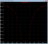
I was playing with the Renardson scheme and reworked its triple to be symmetric and get rather nice wing-spread from it:

Note the scale, the wobble is about 0.0004 variation in gain, and its extending pretty much to +/-48V out of +/-50V rails to (which is nice!).

Taking the feedback point to the output node makes it unstable for part of the cycle, but 20 ohm divider seems to be OK.
The bias voltage is super-sensitive though with 0.1 emitter resistors which may be its Achilles' heel.
I was playing with the Renardson scheme and reworked its triple to be symmetric and get rather nice wing-spread from it:
Note the scale, the wobble is about 0.0004 variation in gain, and its extending pretty much to +/-48V out of +/-50V rails to (which is nice!).
Taking the feedback point to the output node makes it unstable for part of the cycle, but 20 ohm divider seems to be OK.
The bias voltage is super-sensitive though with 0.1 emitter resistors which may be its Achilles' heel.
Last edited:
But the doublecross curves are into something like 80 ohms by the look of it. Compare it to a standard CFP into 8 ohms perhaps?
- Home
- Amplifiers
- Solid State
- Methods to reduce crossover distortion?