Well, the conversation has wandered far from calculating the circuit quiescent amps, volts and resistance values.
I do one thing that is helpful myself: I 'look at' the available voltages and make a reasoned-persons approximation of where I want the synthetic load line to intersect with Zero signal, then back-calculate the effective internal resistance of the valve as if it were a resistor at that point.
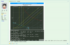
For instance, having a supply of 230 V, I generally use 2/3 Va as the desired quiescent operating point. Simple enough, 2/3 of 230 is about 160 or so. Then, looking at the tube curve graph, I then 'draw a line' up from 160 V, to capture the possible operating currents and grid (negative cathode) voltages that'd be required. In this case, the range is from maybe 2 mA up to 20 mA. I would have chosen something half-way between, about 7.5 mA.
OK, now armed with that, the computation of the anode resistor as well as the cathode resistor becomes trivial. 230 - 160 = 70 volts; current = 7.5 mA. voltage drop is E = IR, R = E/I ... = 70 / 0.0075 = 10,000 ohms. (rounded) For the anode / plate resistor.
Then, the cathode 'grid bias' resistor as well: We've got 7.5 mA, and need a -4V grid effective voltage. So, that's a +4V cathode rise. E = IR, R = E/I = 4 / 0.0075 = 530 ohms. Now the quiescent operating point is chosen ... and done. Plenty of upside and downside operating flexibility.
Lastly, figuring the quiescent anode dissipation to see that the SN7 is not going to glow ... P = IE = 7.5 mA * 160 V = 1.2 watts. Perfectly reasonable for this bomb-durable valve.
Anyway. I've been designing tube circuits of all types for the last 50 years... maybe more. Time moves on. The above calculations are timeless. And no 'tube calculator' needed. Heck... I was just cleaning out one of my to-be-done-later messy drawers, and at the back was my 12 inch Pickett slide rule. Did the above calculations ... on it ... just to remember how, and to prove yet again, that it is just as fast at these estimations as my handy-dandy HP calculator, or my TI calculator, or the idiot-calculator contained in my MacBook Air. Same results.
However, none of the electronica might have survived the 'dropped it out of the car and ran over it with the VW Bug' endurance test, except the slide rule. Actually did that. It wasn't happy, but with a little 'bending on my thigh', it sprang back, and is still working fine, 50 years later.
Just saying...
I do one thing that is helpful myself: I 'look at' the available voltages and make a reasoned-persons approximation of where I want the synthetic load line to intersect with Zero signal, then back-calculate the effective internal resistance of the valve as if it were a resistor at that point.
For instance, having a supply of 230 V, I generally use 2/3 Va as the desired quiescent operating point. Simple enough, 2/3 of 230 is about 160 or so. Then, looking at the tube curve graph, I then 'draw a line' up from 160 V, to capture the possible operating currents and grid (negative cathode) voltages that'd be required. In this case, the range is from maybe 2 mA up to 20 mA. I would have chosen something half-way between, about 7.5 mA.
OK, now armed with that, the computation of the anode resistor as well as the cathode resistor becomes trivial. 230 - 160 = 70 volts; current = 7.5 mA. voltage drop is E = IR, R = E/I ... = 70 / 0.0075 = 10,000 ohms. (rounded) For the anode / plate resistor.
Then, the cathode 'grid bias' resistor as well: We've got 7.5 mA, and need a -4V grid effective voltage. So, that's a +4V cathode rise. E = IR, R = E/I = 4 / 0.0075 = 530 ohms. Now the quiescent operating point is chosen ... and done. Plenty of upside and downside operating flexibility.
Lastly, figuring the quiescent anode dissipation to see that the SN7 is not going to glow ... P = IE = 7.5 mA * 160 V = 1.2 watts. Perfectly reasonable for this bomb-durable valve.
Anyway. I've been designing tube circuits of all types for the last 50 years... maybe more. Time moves on. The above calculations are timeless. And no 'tube calculator' needed. Heck... I was just cleaning out one of my to-be-done-later messy drawers, and at the back was my 12 inch Pickett slide rule. Did the above calculations ... on it ... just to remember how, and to prove yet again, that it is just as fast at these estimations as my handy-dandy HP calculator, or my TI calculator, or the idiot-calculator contained in my MacBook Air. Same results.
However, none of the electronica might have survived the 'dropped it out of the car and ran over it with the VW Bug' endurance test, except the slide rule. Actually did that. It wasn't happy, but with a little 'bending on my thigh', it sprang back, and is still working fine, 50 years later.
Just saying...

Yes, your method we called "approaching". Our tube amp WeChat group has nearly 400 enthusiasts in China. They often use the same way as you, and it means that it is very easy to use,and very fast.
That was & for some still is here. The AM enters at the amplifier input were it is demodulatedAM broadcasting stations are still using high -power radio launchers to facing the public
by what amounts to a grid leak detector formed by the first tube. Good shielding can for the most part fix that.
But if you live beside a 50 KW transmitter could still be a problem.
Grounding wires of things like external TV antennas is another problem, A poor ground connexion
is often a good semiconductor. Unpredictable & often confusing result follows.
Newbies sometimes find a poor solder joint is also a good rectifier, But audio passing thru that
is wrecked!
How good is your wiring, shielding, and filtering?
Do not live near the US Navy 1.5 Megawatt transmitter. It broadcasts at somewhere between 10kHz and 15kHz.
No demodulation needed, it is already in the audio range.
Do not live near the US Navy 1.5 Megawatt transmitter. It broadcasts at somewhere between 10kHz and 15kHz.
No demodulation needed, it is already in the audio range.
I do. So does someone else here (I may be closer). (No, he may be 12 miles closer.)Do not live near the US Navy 1.5 Megawatt
https://en.wikipedia.org/wiki/VLF_Transmitter_Cutler
https://navy-radio.com/commsta/cutler.htm
"...you had to deice manually with baseball bats."
Recent upgrades are controversial b/c they will lay big power cables across the bay, suck more kilowatts than 4 counties, and block some good lobster grounds. So folks say.
Last edited:
PRR,
Sorry, I hope all of those powerful VLF transmitters, whether within the 20kHz audio range, or slightly above the audio range, do not enter into your system, and beat with other frequencies (like CD player 'birdies', switching supplies, etc.).
Sorry, I hope all of those powerful VLF transmitters, whether within the 20kHz audio range, or slightly above the audio range, do not enter into your system, and beat with other frequencies (like CD player 'birdies', switching supplies, etc.).
Wow! I thought four TV and FM stations within a mile were bad.
IIRC that VLF is for comm with subs.
IIRC that VLF is for comm with subs.
Danyixuan DiDiu1,
Thank-you for kindly sharing your method. I can try it with my next design.
Here is the simulator (no cost to use) that helped me design my first tube amp: a 60 Watt KT-88, 12BH7, 6CG7 push-pull amplifier.
https://trioda.com/index.php/en/narzedzia-gb/4216-program-wspomagajacy-dobor-punktu-pracy-triody-gb
While the simulator graph lines are only an approximation of the tubes we use today, it is fun to move the operating point around to learn how tubes work.
David
Thank you David, if you can design the automatic computing program to the more complicated ones, there is a circuit diagram with two-stage power supply coupling for calculation, then almost all problems are solved. We look forward to your new version of calculation tools.
In the following circuit, I can only perform approximate calculations at present, and I haven't found a method that can be calculated accurately.

This is just an example for calculating the work point of DC, which does not mean that there will be such circuits in reality。
In the following circuit, I can only perform approximate calculations at present, and I haven't found a method that can be calculated accurately.
This is just an example for calculating the work point of DC, which does not mean that there will be such circuits in reality。
Now, our calculation method is to decompose the above circuit diagram into an equivalent circuit below.

That thing is so coolI do. So does someone else here (I may be closer). (No, he may be 12 miles closer.)
https://en.wikipedia.org/wiki/VLF_Transmitter_Cutler
https://navy-radio.com/commsta/cutler.htm
"...you had to deice manually with baseball bats."
Recent upgrades are controversial b/c they will lay big power cables across the bay, suck more kilowatts than 4 counties, and block some good lobster grounds. So folks say.
Danyixuan DiDiu1,
I apologize for my lack of clarity in writing. I am not the designer of that clever simulation program, only a user of that program, like your club members.
My understanding of tube design is very limited, and I learned just enough about tubes to build an amplifier that is a modification of an existing design.
It is the only work I have done with tubes, and my wife is glad I did not electrocute myself!
Your circuits look interesting, but I do not have enough knowledge of tube design to make educated comments.
Glad to hear you and your club members use that program as well. Hopefully, the user group at that website can discuss your interesting ideas to further the development of that program.
David
Attachments

Sorry, david,
it is my mistake. I didn't read your text carefully, please forgive me. I believe you will make perfect amplifiers for you.
Yes, it is a very cool program. It brings me and my friends with high efficiency and simplified design to DIY so many tube amps, which brings us a lot of fun. I hope they can improve better program.
And your amp looks so beautiful!
Danyixuan DiDiu1,
Thank you for your kind words. I understand how difficult it is to communicate in English, which is a complicated language, especially if one uses computer translators. You are doing fine!
David
Thank you for your kind words. I understand how difficult it is to communicate in English, which is a complicated language, especially if one uses computer translators. You are doing fine!
David
After a long time of experience, we believe that choosing an anode working current value in the red line area is easy to get accurate results. Below the red line area, the magnifying curve is bent. On it, the width of the voltage is not enough, and the working point may fall outside the work area. You may need to re -select the point again. On the left side of the red area, when the grid voltage is lower than -1V, the grid current will appear in 6SN7.

The illustration method can only be calculated here, and the current in the first two graphics methods is decomposed into equation variables, and the interpretation of the equation group is to obtain an accurate first and second -level anode current value.Now, our calculation method is to decompose the above circuit diagram into an equivalent circuit below.
View attachment 1144497
At one time HP had a VLF Receiver & Comparator for the 60 KHz signal at Bouder, CO.Do not live near the US Navy 1.5 Megawatt transmitter. It broadcasts at somewhere between 10kHz and 15kHz.
We sold these to standards labs, Universities & some of the larger businesses in the electronics buz.
https://www.hpl.hp.com/hpjournal/pdfs/IssuePDFs/1964-10.pdf
I read somewhere 30 yrs ago the USN had a Comm Station running of 18 KHz used
to communicate with submarines while underwater.
R&S had/has quite a bit of measurement equipment such as calibrated recovers & antennas to measure that,
especially as in interference.
Some amatuer radio fans have built equipment for detection of those emissions.
jstewart9,
Thanks for your 'timely' mention of the 60kHz HP receiver . . .
(If I remember correctly, it had a method of outputting co-ordinated universal mean time).
One of my jobs when I worked in the shipyards was to test a USN VLF receiver.
I had to put the vacuum tube VLF receiver and a signal generator into a screen room in order to test the 0.2uV for 10dB S/N ratio at 10kHz. Because this was a shipyard, and due to the limitations of the mains power line filters of the screen room, I had to find a time when all the Welders stopped welding.
And then, there are those who used VLF receivers to 'hear' the VLF signal 'transmitted' from the NASA rocket engines taking off.
Electrons in motion.
fun and games . . .
- Home
- Amplifiers
- Tubes / Valves
- Method of calculating the electronic tube work point from the circuit diagram : Four methods on the picture