Hello, I am Danyixuan DiDiu1. From China, I have a simple way to introduce the work point of the electronic tube work point without labeling the circuit diagram.
I have used this method for more than 20 years, which is very accurate and convenient.
I have used this method for more than 20 years, which is very accurate and convenient.
For example, in the circuit diagram below, there are only electronic tube models, HT voltage and resistance values. If we want to calculate the grid voltage, anode voltage, and anode current of the electronic tube, the subsequent method can be used.

The four -point method is to find four points to define two cross lines, which are dynamic load cables of gate voltage and anode current, and dynamic load lines with anode voltage and anode current. The intersection of the line is the actual working point.
Just define two working current points.
The current point must be selected in the working area of this electronic tube, and it is meaningless outside the working area. And it is best to mark the accurate anode current line, so that the drawing is more accurate.
For example, in the figure below:

In the diagram of this 6SN7 electronic tube, the vertical direction per grid is 1mA, and two current points are selected near the central area. However, in order to draw the line accurate, two points that are far away will be selected, which is too close to cause errors. For example, we take 3MA-10mA.
Just define two working current points.
The current point must be selected in the working area of this electronic tube, and it is meaningless outside the working area. And it is best to mark the accurate anode current line, so that the drawing is more accurate.
For example, in the figure below:
In the diagram of this 6SN7 electronic tube, the vertical direction per grid is 1mA, and two current points are selected near the central area. However, in order to draw the line accurate, two points that are far away will be selected, which is too close to cause errors. For example, we take 3MA-10mA.
The first point: Assuming the screen flow of 3mA, the voltage on the cathode resistance is 0.003max910ohm = 2.73V. This is the partial voltage value of the grid obtained -2.73V. We marked it on the map. This position is marked with the dynamic load of the gate voltage and anode current, and the anode voltage does not need to be considered.

In fact, this picture is a three -dimensional relationship map: the anode voltage in the X -axis direction, the anode current in the direction of the Y axis, and the gate voltage in the area is in the direction of the Z axis.
In fact, this picture is a three -dimensional relationship map: the anode voltage in the X -axis direction, the anode current in the direction of the Y axis, and the gate voltage in the area is in the direction of the Z axis.
The second point: still assume that the screen flow is 3mA, then (anode+cathode) resistance pressure is reduced to 0.003max (12000ohm+910ohm) = 38.73V, anode voltage = 230V-38.73V = 191.27V, and the point is also marked to the graph to the graph superior.

The third point: Assuming that the anode current is 10mA, the grid voltage is equal to -9.1V, as shown in the figure.

The fourth point: Assuming that the anode current is 10mA, the anode voltage is equal to 100.90V, as shown in the figure.

The two dynamic load cables intersect, the anode current obtained at the intersection point is 5.4mA, and the anode voltage is 160V. This intersection point is the DC working point. The gate DC voltage can be obtained by -0.0054max910ohm = -4.914V.

The principle of this calculation method is that because the cathode resistance determines the only cathode dynamic load line, and anode resistance determines the only anode dynamic load, the DC working point can only be at the common working point of these two lines.
If the circuit diagram is as shown below, use (12K+5.6K) = 17.6K as an anode resistance. Use the above methods to calculate the DC working point.

However, in this case, the anode communication dynamic load of 6SN7 is not on the same line as DC dynamic load.
Last edited:

2W is more convenient for welding, ensuring the firmness of the solder joints, and inhibiting the membrane resistance noise caused by slight vibration. Of course, if use PCB, I will also use 1/8W or 1/4W.


I use the Universal Tube Loadline Calculator to work on the operating point for my tube amp projects.
https://www.vtadiy.com/loadline-calculators/loadline-calculator/
https://www.vtadiy.com/loadline-calculators/loadline-calculator/
I have also used the Universal Tube Loadline Calculator, but I think these are two different calculation directions.
Good suggestions, but in this circuit, Grid Stoppers is not to stop the oscillation, but to form a RC low -pass filter to prevent high frequency from entering the amplifier. Because in the later amplifier circuit, two -level anode feedback is used, and higher frequencies will form a considerable phase movement in the negative feedback loop capacitor.
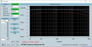
This is the frequency characteristics of the preamplifier after using the 3 Grid Stoppers.

Although the extension of the high frequency direction is not flat enough, the amplifier has obtained a relatively satisfactory distortion characteristics.

Although the extension of the high frequency direction is not flat enough, the amplifier has obtained a relatively satisfactory distortion characteristics.
Attachments
There are other interesting reasons.In the cities where I live, more than 20 million people live, and some official AM broadcasting stations are still using high -power radio launchers to facing the public. The high-sensitivity tube amp are easy to receive them even without detectors. After using Grid Stoppers,it is quiet.
- Home
- Amplifiers
- Tubes / Valves
- Method of calculating the electronic tube work point from the circuit diagram : Four methods on the picture