Please check the supply polarities also. They don't coincide with the semiconductors besides Q1, Q4 😉.
Best regards!
Best regards!
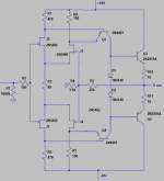
i updated the drawing, i desoldered them and checked in a transistor tester, turned out to be both jfets p and n channel.
also found all resistor values.
but one diode cracked, couldnt measure if its a zener or not.
also found all resistor values.
but one diode cracked, couldnt measure if its a zener or not.
Hi GP, reminds me of a project I had years ago with a Robertson 4010. It had potted modules also. Heated and drawn out circuit just like you are doing. It all worked in the end. Keep up the good work!
i think i got it,
the circuit seems to produce a clean signal, (i had to change some components since ltspice didnt have them)
and Gain is about the same as with the working module.
and thanks for pointing out the wrong polarity.. i just checked with the working unit, it was indeed wrong.
yea, that will be it. im gonna make a pair of identical pcb's and this preamp should be as good as new. i wont pot them obviously, just thermally connect all transistors together.

simulation vs reality, about the same Vin to Vout ratio at 1khz. im happy.


the circuit seems to produce a clean signal, (i had to change some components since ltspice didnt have them)
and Gain is about the same as with the working module.
and thanks for pointing out the wrong polarity.. i just checked with the working unit, it was indeed wrong.
yea, that will be it. im gonna make a pair of identical pcb's and this preamp should be as good as new. i wont pot them obviously, just thermally connect all transistors together.
simulation vs reality, about the same Vin to Vout ratio at 1khz. im happy.
The first thing I thought when I read the title of the post is that the culprit of the violent noises and crackles was the same fault that many of us suffered with the differential TR 2SA798 of the "damn" Sansui AU4900.
The method of encapsulating everything was used at one time to protect "exclusive" designs from illegal copying .......
Currently that does not happen anymore, the manufacturers do not directly provide or allow access to the circuits.
Great guys!
My congratulations for having put it into operation "normal", it is a reward for effort that is unparalleled with "throw it away and buy something new", so common in consumer society ......
And once we consume all the resources of the planet, what next?
Congrats also from me for successfully debunking this circuitry! This is DIY at it's best 😀!
And after all, this is a very fine looking unit, a gem, so to speak.
Best regards!
And after all, this is a very fine looking unit, a gem, so to speak.
Best regards!
Last edited:

Compare this circuit to the output module of Mark Levinson JC 2
(John Curl) and you see that Metaxas in fact had something to hide.
(John Curl) and you see that Metaxas in fact had something to hide.
Hi gamerpaddy,
I might be nit picking as many jfets are symmetrical meaning that drain and source can be swapped. However, I don't know if that's the case for the jfets used in the module besides making the drawing somewhat clearer. Looking at the pictures you posted of the module it seems that the jfets aren't used with drain and source swapped.
Mogens
And here ML JC2 for comparison (feedback resistor pair not shown) :
https://www.diyaudio.com/forums/sol...hematic-website-wrong-john-8.html#post1932993
https://www.diyaudio.com/forums/sol...hematic-website-wrong-john-8.html#post1932993
Just for fun, here's a link to that Metaxas designed early DIY project I'd mentioned earlier.
MAS Technology Do It Yourself
MAS Technology Do It Yourself
And here ML JC2 for comparison (feedback resistor pair not shown) :
https://www.diyaudio.com/forums/sol...hematic-website-wrong-john-8.html#post1932993
not quite identical, is it...
Just for fun, here's a link to that Metaxas designed early DIY project I'd mentioned earlier.
MAS Technology Do It Yourself
That is very old page I remember well, i built that phono preamp. Not the power supply though. I do not have it anymore, gave it to a friend long time ago. Not sure what happened to it. It was ok, but little too sharp sounding. May be it was my choice of transistors.
thanks Ketje, i redrawn my schematic before i saw your post, turned out to be almost identical
i also flipped T2 & T4 as mentioned by mkc simulation was still fine with it.
also removed the second diode which i dont even know what it exactly was (no markins on the original part, and it was cracked) but it doesnt seem to make any difference in the simulation.
i hope the parts i ordered are roughly matched, i dont wanna spent too much money on lots of jfets just to find 4 pairs that work.
also made a pcb with THT parts.


files and stuff can be found here
Metaxas K20 gain cell for CP-1 preamp -
EasyEDA
i also flipped T2 & T4 as mentioned by mkc simulation was still fine with it.
also removed the second diode which i dont even know what it exactly was (no markins on the original part, and it was cracked) but it doesnt seem to make any difference in the simulation.
i hope the parts i ordered are roughly matched, i dont wanna spent too much money on lots of jfets just to find 4 pairs that work.
also made a pcb with THT parts.
files and stuff can be found here
Metaxas K20 gain cell for CP-1 preamp -
EasyEDA
Last edited:
- Home
- Source & Line
- Analog Line Level
- Metaxas CP-1 - Impossible repair? Crackling & Popping on one channel.