There are no TO3 versions of 2SC/2SA devices, they were always made in plastic.
The MJL's are copies of the Toshiba's, no chance of TO3's.
The MJL's are copies of the Toshiba's, no chance of TO3's.
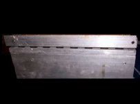
I think it's a little hard to generalize about plastic vs metal cases. Not all plastic cases are created equally. For example, take a look at these Toshiba cases:
http://www.diyaudio.com/forums/showthread.php?postid=561160#post561160
The entire back is metal. These particular cases are still only rated at 150W.
http://www.diyaudio.com/forums/showthread.php?postid=561160#post561160
The entire back is metal. These particular cases are still only rated at 150W.
derating...
Assuming the manufacturers are being 'honest' in their ratings, the biggest differentiating factor in favour of to3 packages is the increased power handling.
To examine a specific example, the 21193/4 type parts (to264-200w, to3-250w), at a dissipation of 50w/device, if the package is at 60c, die at ~95c, after derating properly, you need twice as many of the mjl21194 than you do of the mj21194, for the same capabilities...and in this respect the mjl21194 is one of the best output bjt's around, most are worse.
Most of the other distinctions are personal preference, the die is the same, the bond out wires are the same. In a to3 package you just get to use more of the capabilities of the chunk of silicon inside.
If both are mounted properly there is no way the ~1cm square of contact metal in a plastic package will ever compete with the thermal transfer area of a to3 case. The same material used as the insulation will be more effective for to3, by virtue of larger surface and better clamping
Perhaps the best answer is to follow Nelson Pass example and use transistors at a small fraction of their rated capability, then it really doesn't matter which of the packages you use, and there is no doubt the plastic is much easier to mount.
Stuart
Sanken has some devices in such package (2-screw mount) rated even at 200W.
http://www.sanken-ele.co.jp/en/
But this value, maximum power dissipation, is not about copper plate area, as it is theoretical. It depends only on maximum allowed die operation temperature and on thermal resistance die-to-copper. Considering this, it's easy to understand why power FETs usually have higher theoretical dissipation, say 300W in TO-247 package, because FETs have both these parameters better.
mosfets have higher Tj max...
...and all else being equal this is a big part of why the package can dissipate more power...the fact that mosfets can also be fabricated in larger die sizes helps for any application that can use the parameters that the physically larger part implies...higher capacitances, etc
Stuart
...and all else being equal this is a big part of why the package can dissipate more power...the fact that mosfets can also be fabricated in larger die sizes helps for any application that can use the parameters that the physically larger part implies...higher capacitances, etc
Stuart
Re: derating...
Addition :
Dies are connected straight to the TO3 base plate, unlike other case types, big difference in heat transfer.
And the heat from the die is not transferred to the case 2-dimensionally, but in all directions.
The Pass rule is common sense, but still a shame the TO3 is out of fashion.
Thermal advantage is well worth the added device mounting effort.
I suppose Alme's link should refer to a Sanken MT200 case ?
Any idea why this case is used for Ring-emitter(multi-emitter) devices?
Stuart Easson said:If both are mounted properly there is no way the ~1cm square of contact metal in a plastic package will ever compete with the thermal transfer area of a to3 case. The same material used as the insulation will be more effective for to3, by virtue of larger surface and better clamping
Addition :
Dies are connected straight to the TO3 base plate, unlike other case types, big difference in heat transfer.
And the heat from the die is not transferred to the case 2-dimensionally, but in all directions.
The Pass rule is common sense, but still a shame the TO3 is out of fashion.
Thermal advantage is well worth the added device mounting effort.
I suppose Alme's link should refer to a Sanken MT200 case ?
Any idea why this case is used for Ring-emitter(multi-emitter) devices?
"Dies are connected straight to the TO3 base plate, unlike other case types, big difference in heat transfer.
And the heat from the die is not transferred to the case 2-dimensionally, but in all directions."
Unless the dies are not mounted to the metal mount of the TO-247's then TO-3 is far better but I have to think that the die is directly mounted to the metal base of the TO-247 as well. So heat dissipation efficiency should'nt be that much different.....
Mark
depends...
can't speak for other manufacturers, but the thermal resistance from die to case of the on-semi 21193/4 to3 and plastic parts is spec'ced the same, 0.7c/w. So I assume they have the same mounting arrangement. The real difference is in the case to heatsink or case to insulator to heatsink, and then the to3 wins big time.
When I get back I'll set up a simple experiment to measure the difference, same die, different package, same heatsink, same power, measure temps on and behind device...
For now I'll keep using to3 for pre-drilled heatsinks and plastic packages for any that I have to drill...
Stuart
TO3 devices only have two pins, TO247 have three.
imo, it seems that with three pin devices the third pin is connected to a metal plate between device sink and die.
All of the pictures i have seen of plastics on threads on Fakes here at diyaudio seemed to show the same edge on device sinks.
with an added plate between sink and die there are two soldering joints, thermally that should make a difference.
The plastic cases i opened up showed a case sink with a plate holding the die soldered on it, i figured it is cheaper to make them like that.
Those were old devices, could be that all plastic devices nowadays have one piece sinks.
Another advantage of TO3's is the possibility of putting a heatsink on the TO3 top, or soldering the lead straight to the TO3 case.
Musical Fidelity did a lot of that with their early designs, i loved the originality.
Ever touched the heatsink of those MF models ?
Not at all, U-papa Epops. 
How are TO220-TO247 etc. case sinks nowadays ?
A single sink with a machine pressed surface for die mounting or a case sink with a die mounting plate attached to it ?
How are TO220-TO247 etc. case sinks nowadays ?
A single sink with a machine pressed surface for die mounting or a case sink with a die mounting plate attached to it ?
Upupa Epops,
I figured as much already from the 1-2, and symbol, in the schematic for Q23,Q26.
The reasoning for using the sink directly as collector?
I figured as much already from the 1-2, and symbol, in the schematic for Q23,Q26.
The reasoning for using the sink directly as collector?
Reasoning ? " Superwire " as rail line ( prism 10*20 mm, copper ). Precise thermal loop ( thermal sensing transistors Q 21, 24 are on bottom side, bolted from side to prism ). Easy mounting - block is fully functional without heatsink, which caused also very friendly repairing ( what is offten forgoten by DIYers ).
In high power TO-3 devices the die is allways attached to an intermediate thick copper coin [heat spreader] that is then attached to the steel case. In most TO-3 fakes the copper plate is missing and this reduces power handling dramatically since steel has much higher thermal resistance than copper
In the other hand, in plastic TO-220, TO-247 and TO-3P/TO-262 devices the die is directly attached to the rear copper plate of the device so the same thermal resistance between junction and heatsink is obtained with less contact surface than in a TO-3. The collector leg of plastic devices is molded directly as part of the copper plate, it's not soldered [I wonder how this is done]
Heat transfer in plastic cases is actually more effective than in metal cases. However, in a TO-3 case the die and the bonding wires are allowed to dilate freely since there is no plastic resin filling the case while in plastic devices the resin is actually the limiting factor for the maximum operating temperature. So the only advantage of metal cases is the higher maximum operating temperature, allowing for a higher dissipation ratng given the same heatsink, but this extended temperature range isn't usually practical due to SOA and reliability constraints
Also note that the optimum mounting method for plastic cases is by means of a metal rail pressing the bodies of the devices against the heatsink, single screw mounting isn't optimum but does it's job for medium and low dissipation applications. Clip mounting is also very comfortable for low to medium pwer dissipations, even at high powers provided enough torque, and there are no screws to get loose
Hi Eva,
i wondered what took the expert so long.
You are saying its the other way around: TO3's use an intermediate plate between die and case sink, other models do not !
Then what is the function of the square lines i see on the opened devices you and others posted on the thread on fakes ?
For holding the plastic cover?
Molding the leg is easy, just press hard untill the sink material reaches its plastic deformation state.
The same technique is used for sail boat rigs, tensioners are pressed on to steel wires, such a connection withstands incredible forces.
From classes i remember that on moleculair scale the intersection of both materials even becomes intermixed.
Upupa Epops, do you mind if i ask which kind of Mosfets are used in your design for Q23,Q26 ?
I don't know the purpose of these prominences [lines, points, etc..] but TO-3 devices also have them
This is an ancient MJ15022.
Oops! The base bonding wire was broken when opening the metal can 🙁
Note that the thick heat spreading copper coin is designed to use as much surface as posible
Nearly all the dies I've seen are soldered to the copper plates, check out the solder leftovers on the picture [they have been obviously cleaned]
This is an ancient MJ15022.
An externally hosted image should be here but it was not working when we last tested it.
Oops! The base bonding wire was broken when opening the metal can 🙁
Note that the thick heat spreading copper coin is designed to use as much surface as posible
Nearly all the dies I've seen are soldered to the copper plates, check out the solder leftovers on the picture [they have been obviously cleaned]
- Status
- Not open for further replies.
- Home
- Amplifiers
- Solid State
- metal vs plastic transistors