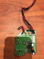
It seems to me that you don't have full continuity of the pot connections, specifically the earth or ground end of the circuits. Check the PCB for modifications that may have been done to make the previous pot fit and work correctly. Check with a multimeter that the new pot works and sweeps its resistance value like any pot should when out of circuit - both left and right channel sections, from minimum to maximum rotation. Check that the grounded ends of the pots indeed make connection with the signal ground at the input or speaker ground.
Ah, as_audio beat me to it!
Ah, as_audio beat me to it!
Last edited:
Thank you. What they did was to solder the ground capacitor (I think) directly to the body of the POT which I replicated as a last resort. Still no good.
I wrote use an ohmmeter to check the connection to signal ground.
It seems to be missing on the two pins as described and so a wire
connection from both pins to signal ground on this board will re-
establish the usual function.
I however fail to see where this ground is on the picture in post 12.
It seems to be missing on the two pins as described and so a wire
connection from both pins to signal ground on this board will re-
establish the usual function.
I however fail to see where this ground is on the picture in post 12.
Did you remove it again ?
If so you can establish the connections back with a thin wire soldered
to top and bottom of the respective pin hole sides.
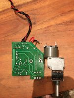
On the first picture you can see the connections to the "ground plane".
This connection is missing on the other side due to multiple desoldering.
New solder connection for the pot alone can only be applied to the underside.
If not sure where to place a corrective wire connection have a close look.
If so you can establish the connections back with a thin wire soldered
to top and bottom of the respective pin hole sides.
On the first picture you can see the connections to the "ground plane".
This connection is missing on the other side due to multiple desoldering.
New solder connection for the pot alone can only be applied to the underside.
If not sure where to place a corrective wire connection have a close look.
Did you remove it again ?
No choice really.
If so you can establish the connections back with a thin wire soldered to top and bottom of the respective pin hole sides.
If not sure where to place a corrective wire connection have a close look.
I am not entirely sure no, and thanks for the input so far. It's either a small wire between the two largest holes or between the two pin holes beside "VR1" in picture 1.
Again, thanks for your help. Can you guess I've never so much as looked at a a soldering iron let alone attempt a repair that someone else has made a balls of?
I thought it was clear that a potentiometer has three (solder pins here)
connectors, two times for stereo, i. e. six in this case.
The two big large holes and their respective solder lugs are for attachment
of the gear case only.
I already described the position of missing ground "through hole" connections
in post 20 and 27. It is on the two low side points of your post 1 picture.
It is easy to see that these two solder points do not connect to anything on
the shown side of the board. The necessary connection to ground has been
on the other side. Read about "pcb vias" if you do not know about it. These
can easily break when removing parts from the pcb. This is what happened.
Yes, "the two pin holes beside "VR1" " on the left picture of post 28. Connection
to ground for both of them.
Last edited:
AS- last question. Am I connecting the pin holes together or to another point on the board?
Thank you
Thank you
AS- I don’t know where ground is. I have never done this before. Can you help me identify where I need to connect the ground pins to.
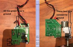
These two pins on the pot must electrically connect to the large area of green print which is ground.
If you are not able to solder on the underside of the board (which I can understand if you have never done this before) then wrap those two pins with wire on the top to connect them together and just loop it over the edge of the board and solder to the other side.
The green shiny varnish on the board will need scraping away in order to solder to it.
Attachments
@ Mooly- literally anywhere in the shiny green area?
If I look at your large arrow, there is a soldered raised area to the right of the tip where two underside connections connect to the ground. Am I going for something similar, albeit less elegant?
My soldering turns out to be quite good so happy to solder the wires from the pins from the underside to the top.
AM and Mooly- THANK YOU. I now have a fully functioning AMP that i was convinced was destined for the slag heap. Had to re-solder one of the stereo pins as only one speaker was working. Thank christ it wasnt a blown speaker.
Thanks again and Merry Christmas.
Edit- as daft as it seems, the sound is better than ever!
Thanks again and Merry Christmas.
Edit- as daft as it seems, the sound is better than ever!
Last edited:
 you sussed it out.
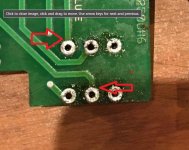
Just to add it is very easy to crack and lift the print around the solder pads if you are not used to working on such things. That can cause intermittent issues and the breaks can be invisible.
If that happens then just scrape the varnish away and solder a strand of wire over the area.
Hopefully all is good 🙂
This shows where such breaks occur which is usually where the solder pad and print meet.
If that happens then just scrape the varnish away and solder a strand of wire over the area.
Hopefully all is good 🙂
This shows where such breaks occur which is usually where the solder pad and print meet.
Attachments
I think it was a combo of the last guy boshing the wrong pot in to begin with followed by my outstanding lack of understanding that contributed to the problems. There is the tiniest whine from the tweeter, but you literally have to nearly insert the wave guide in your ear to hear it but I don't want to see another soldering iron ever again!
I have no clue how the change influenced the sound, but bass is waay deeper without losing any detail.
In any event, I am indebted to you and AM. I may just sell this AMP quick however!
I have no clue how the change influenced the sound, but bass is waay deeper without losing any detail.
In any event, I am indebted to you and AM. I may just sell this AMP quick however!
- Home
- Amplifiers
- Solid State
- Messed up POTS