What setting should my meter be on to test fets 20m,200k,20k,2k,200
The setting at 5 o'clock -|>- that is your diode check.
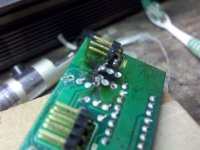
I dont know if you can see in the picture but when i was brushing the driver card with a toothbrush one of the traces bent up. Will it be ok as long as i make sure that it is soldered back to the leg of the transistor? Also I'm having trouble getting the BD140 that i ordered to fit through the holes on the board do i need to carefully file the legs to make them a little smaller?
Attachments
The legs should fit with little or no resistance if all of the solder is removed from the via and there is no damage to the via.
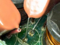
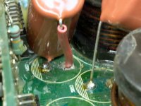
When you solder the transistors on a board that's damaged, like this one, you need to look at the top and bottom to see if there are traces on one or both sides of the board for each leg of the component. As you can see in the next two photos (links due to file size), there is only a trace on the top of the board for the 3rd leg and a trace only on the bottom for the middle leg. For the first leg, there is a trace on the top and bottom, you either have to make sure that solder flows from one side of the board to the other (which means that the via is intact) or you have to solder from both sides. Here, the vias were intact so the solder flowed to the other side of the board. I'll have to solder the center leg from the top. Since the trace is likely weak for leg 1 of Q16, you should install a jumper between the leg of the transistor and the pin on the large connector. That will ensure that the connection will be reliable when the amp is subjected to vibration.
http://www.bcae1.com/temp/IMG_9909.JPG
http://www.bcae1.com/temp/IMG_9911.JPG
http://www.bcae1.com/temp/IMG_1076.JPG
http://www.bcae1.com/temp/IMG_1079.JPG
Last edited:

I have replaced all the 3205s, FQP50n06s all the gate resistors 2 bd140s on the power supply driver card and 3 10uf/200v capacitors. There was one irf9640 and one FB31N20D transistor in the class d outputs theat were shorted so I removed all of them all the rest of the outputs checked out ok. I clamped all the transistors to the heat sink and put power to the amp with a 10 amp fuse in line with the positive wire the protect light comes on and stays on so then I removed the power supply driver card and the protect light doesn't light up at all but about 3 seconds with the power to it i can here the relay click. What should I check next?
If you only replaced the shorted transistors in the sub channel, it's not likely to be reliable.
Reinstall the driver board and monitor the DC voltage on the center leg of the output transistors in the sub channel. Do you see more than a fraction of a volt DC as the amp attempts to power up?
Reinstall the driver board and monitor the DC voltage on the center leg of the output transistors in the sub channel. Do you see more than a fraction of a volt DC as the amp attempts to power up?
There is 00.1 mv on the center pad of all the class d section transistors. With the driver card in the protect light comes on and the relay does not click. With the driver card out the relay will click about 3 seconds after power is applied but the green power/red protect light does not light up at all.
- Status
- This old topic is closed. If you want to reopen this topic, contact a moderator using the "Report Post" button.
- Home
- General Interest
- Car Audio
- Memphis 16-MCH1300 help