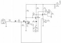
I have a feeling if you bias the first trany with a typical divider you can get rid of the bootstrap resistor all together. (unless the tape head makes a difference, which I think it does or why did they bother with it)
We have people comming over for Easter dinner so I have to go spank the turkey (not the monkey). Will get back to this hopfuley tommorow. Still might post this in solid state, maybe someone there knows why that huge 10hz peak is there? You need to find out if you need to reproduce it in your opamp circuit, which will make it a lot more complicated and dificult to stabilize.
Very good, I have tried to sim a tape head by using a inductor and a resistor in series with it but I haven't spent much time on it yet.
And I am thinking about just going right into an op amp design.
It looks as you are getting pretty much the same frequency response that I am getting. jer
P.S. Happy Easter everyone !!!
And I am thinking about just going right into an op amp design.
It looks as you are getting pretty much the same frequency response that I am getting. jer
P.S. Happy Easter everyone !!!
What values did you use for the tape head? Did you find them somewhere?
Yeah same f response, huge 10hz peak and its bugging me why its there. Are you going to reproduce that peak?
Yeah same f response, huge 10hz peak and its bugging me why its there. Are you going to reproduce that peak?
I only tried it once with a few values and it made no difference on the low frequncy peak for the vaues I did try and circiut maker would error unless I had A resistor in series with the inductor.
So then I decided to try to find some tape head specs and I haven't done so yet as I don't remember what any typical values for them from yesteryears are. jer
So then I decided to try to find some tape head specs and I haven't done so yet as I don't remember what any typical values for them from yesteryears are. jer
I don't think it would be nessesary to reproduce that peak as it seems to drop by 30hz to 40hz.
But I will see once I get on it, as I believe it is a function of the value of the input capacitor. jer
But I will see once I get on it, as I believe it is a function of the value of the input capacitor. jer
The head inductance seems to make little difference but the resistance does. I assume its quite high (the head cant put out a lot of current).

I was adding the the inductance in paralle with input as the tape head would in the circuit, But may be that is why I didn't see much change.
As to your sims I was expecting a drop in the 10hz peak when the inductance is added. Very interesting indeed. jer
As to your sims I was expecting a drop in the 10hz peak when the inductance is added. Very interesting indeed. jer
The voltage out of a perfect source dosnt change with load so anything in paralell dosnt effect the voltage out.
Just simed with no inductor, didnt chage anything. Its the resistive load that makes the difference.
Just simed with no inductor, didnt chage anything. Its the resistive load that makes the difference.
Found some tape head info. goining to try a typical 500ohm, .35 henry head.
Tape Head Coil Resistance
Tape Head Coil Resistance
Last edited:

Last edited:

Yes, but I wonder what the actual resistance is becuase there are 30 or 70 tape head and I don't remember if it was said that they are in series or paralell?
I use a resistances between 100 to 10k ohms .
Iwill go back and check. jer
I use a resistances between 100 to 10k ohms .
Iwill go back and check. jer
I use a resistances between 100 to 10k ohms .
This makes a huge difference.
there are 30 or 70 tape head
I cant see that there all in parallel or they would load each other down and greatly reduce the output. They must switch in when needed?
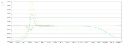
I am curious about the high freqency roll off.
It is said that the corner frequency of the roll off is the frequency where the response is 3db down.
The curve cleary shows that the slope starts about 6khz and is down about 3db at around 12khz.
If this is correct then it could be a duplicating machine eq compensation.
Also according to the curve a simple preamp could be used with a low pass and a high pass shelving eq set at 100hz and 12.5khz and could be trimmed to how one desires as neccessary without any degradation to the playback quality.
What do you think? jer
There are 35 tapes heads all in series. So you can assume a fairly high head impedance.I cant see that there all in parallel or they would load each other down and greatly reduce the output. They must switch in when needed?
BTW, I removed C4 from the circuit and there is no difference in the performance. So I am hunting down a nice low voltage film cap for the spot but failing that then a 0.47uf electrolytic will suit.
Its my theory that the bass bump is a circuit aberration. The tape sets offered don't seem to have any real deep bass on them. 40Hz might be the lowest tones that are recorded.
- Status
- Not open for further replies.
- Home
- Live Sound
- Instruments and Amps
- Mellotron preamp schematic