Hi,
before building the 100W+ amplifier with 6P42S, I have decided to build a smaller amplifier for use with portable speakers for the times when I need to play something not at home.
I would need something around 25W of power output (and preferably make the amp not very big), so, here's what I have considered:
1. 6S33S SE - should give 15-20W, but requires a lot of power for the filaments and a lot of current (something like 450mA for stereo) for the plate, making me think about gas filled rectifiers again.
2. 6L6 PP - I have a lot of these tubes, the datasheet says that I should get about 26W in class AB1. The datasheet recommends 360V power supply with maximum current ~300mA for stereo, which is almost as bad as the 6S33S.
3. EL84 PP - I only have a couple of these and they are fairly expensive (8EUR), but smaller than 6L6 and the datasheet says I should get about 17W in pentode mode, with the power supply requirements are the lowest - 300V with max current of 220mA for stereo.
4. Something else? I would like to avoid tubes with top caps for this project.
A though about the first (6S3S and second (6L6) options - The 6S33S SE produces 15W for 200V*200mA=40W anode power dissipation (IIRC the power consumption of a SE amp does not change at full volume). However, 6L6 produces 25W and consumes 360V*93mA=33.5W at idle and 52W at full power. Shouldn't it be more efficient, being a pentode and operating in class AB? As it is, it pretty much consumes the same amount of power as 6S33S SE, except for the heaters.
Now, for the power supply part - for this project, I'd like to avoid tubes with top caps, which rules out damper diodes and gas rectifiers. I have a couple of 5C8S which are rated for 420mA DC and 1.2A peak (the datasheet does not specify whether this is for one or both plates together), though for the EL84 PP variant, a 5U4G would most likely be enough.
How much does the rectifier sag affect output? The datasheet for 6L6 says that the recommended circuit uses 93mA per channel at idle and 147mA per channel at max power. Simulating the power supply on PSUD2 with 900VCT transformer, 5C8S and choke input. results in 350V at idle and 331V on full power. Would that noticeably affect the output?
Using a cap input filter (with a 8uF cap) and a 700VCT transformer results in 360V at idle and 314V at full load, which is worse than with choke input.
Would the sag result in more distortion at high volume, or just less power than I thought?
Attachments
Hi,
Why on earth would you want a valve amplifier for a portable
application ? TBH I'm not sure what you mean by portable.
A quality 25W valve amplifier is wasted if occasionally used.
rgds, sreten.
Why on earth would you want a valve amplifier for a portable
application ? TBH I'm not sure what you mean by portable.
A quality 25W valve amplifier is wasted if occasionally used.
rgds, sreten.
You can get 20 WPC from the 6П14П-ЕВ (6p14p-ev), AKA EL84M, which is a genuine 7189 equivalent, by following Sherwood's S5000 "recipe". Any tube from the 6BL8/6U8/6GH8 group is a satisfactory replacement for the "extinct" 7199.
Stop fretting over B+ rail sag. Use high PIV Schottky diodes in the rectifier role. The Schottky diodes are every bit as quiet as vacuum rectifiers. "Soften" B+ rise by inserting a CL-90 inrush current limiting thermistor between the Schottkys and the PSU filter.
Stop fretting over B+ rail sag. Use high PIV Schottky diodes in the rectifier role. The Schottky diodes are every bit as quiet as vacuum rectifiers.
"Soften" B+ rise by inserting a CL-90 inrush current limiting thermistor between the Schottkys and the PSU filter.Attachments
Hi,
Why on earth would you want a valve amplifier for a portable
application ? TBH I'm not sure what you mean by portable.
A quality 25W valve amplifier is wasted if occasionally used.
rgds, sreten.
Because I want to build yet another valve amplifier and want to justify it 🙂. That is, if I build something, I want it to be useful, even if it used only occasionally. Also, I think that by making this amplifier I am going to learn more about push-pull operation and pentodes before attempting the 100W+ amp.
By portable I mean that I can put it in an appropriate suitcase and carry it (and the speakers) to wherever I need. No need for battery operation.
Oh, and I do not want to use silicon diodes unless I can't do it any other way - I want this amplifier (like the others) to be similar to what I could build if this was the 1950s. So, it's vacuum, gas or selenium rectifiers for me.
Oh, and I do not want to use silicon diodes unless I can't do it any other way - I want this amplifier (like the others) to be similar to what I could build if this was the 1950s. So, it's vacuum, gas or selenium rectifiers for me.
Selenium rectifiers are ticking, toxic, time bombs. Forget them! Among the "common" rectifiers, the GZ34/5AR4 has the lowest forward drop and should "sag" the least. You can do better with damper diodes.
BTW, silicon diodes were available in the 1950s. 😉 As a youngster, I "fried" a M500, a very early 500 mA. part.
Selenium rectifiers are not suitable for new devices. Got it.
The datasheet for 5AR4 says that the tube is rated for max 250mA DC output.
Still, I like the 6L6 option (also I have about 18 6П3С), however, the number bother me somewhat.
Isn't push-pull class AB using pentodes supposed to be more efficient than SE using a triode?
However, it looks like (ignoring heaters) the 6L6 PP amp recommended in the datasheet consumes almost as much power as the 6S33S amp. Why is it so? Is the 6S33S very efficient as a triode or, conversely, is the 6L6 very inefficient as a pentode?
The 6П3С-E (6p3s-e) is good. Without the special characteristics indication, the tubes are "ordinary".
5AR4 is a good rectifier..but expensive. Two 5V4's in parallel should also work. Two 6AU4 or two 6DE4 damper diodes should also work fine. Have a separate 6.3 v 3 amp winding or transformer for the heaters...one doesn't need a heater-cathode short putting all the heaters in the amp at B plus...
As far as rectifier tubes in parallel goes, remember the old RCA color TV sets (like the early CTC series) where the power transformer put out something like 800 volts at 400 ma and two 5U4 rectifiers were connected in parallel...
As far as rectifier tubes in parallel goes, remember the old RCA color TV sets (like the early CTC series) where the power transformer put out something like 800 volts at 400 ma and two 5U4 rectifiers were connected in parallel...
NOS 5AR4s are ridiculously expensive. However, the current production Sovtek 5AR4, which costs about $20, is highly satisfactory, once the series SS diode tweak is installed.
Hmm... I guess I'll have to try the rectifiers I have first and see if the power supply sag actually affects the sound in a way that is noticeable and objectionable (if it only results in dynamic range compression at full volume it may even be a good thing). If yes, I can then try the damper diodes or more expensive tubes.
Could recommend me a circuit with two 6L6s in push-pull that is better than the recommendation in the datasheet?
Once I buy the output transformers I am kinda committed, so I really want to figure things out before doing that. With my previous amplifier, I bought a "universal" output transformer (Hammond 125ESE) so I could try various options before buying a good transformer but with a single primary impedance.
However, I do not see such an option for PP ~25W output (125E is rated for 80mA and 15W), this is why I am asking these questions.
Could you also point me to a good source for learning how to design a PP class AB amplifier with pentodes?
By portable I mean that I can put it in an appropriate suitcase and carry it (and the speakers) to wherever I need. No need for battery operation.
At one time valve radios worked off batteries.
They had I think 90 volt batteries for B+.
I suspect they had another battery for heaters.
At one time valve radios worked off batteries.
They had I think 90 volt batteries for B+.
I suspect they had another battery for heaters.
The battery tubes worked with as little as 45 V. My dad's radio used a 67.5 V. B+ battery. You are correct about some units using 90 V. The tube complement in dad's radio was a 1R5, a 1U4, a 1S5, and a 3S4. Pretty much an AA5, minus the rectifier. 4X 1.5 V. "D" cells completed the on the go power package.
Notice the 22.5 V. increment. A 22.5 V. battery went into a hearing aid.
Could recommend me a circuit with two 6L6s in push-pull that is better than the recommendation in the datasheet?
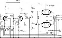
Sure! The H/K Cit. 5 is a superior implementation of Mullard style circuitry. Any 6L6GC "equivalent", including the 6П3С-Е, should be fine as the "finals". The 12BY7 is becoming scarce; so, I've provided a 6922 (6H23П-ЕB) cascode to take its place.
This "bad boy" will easily make 40+ WPC. Definitely use damper diodes, if you vacuum rectify the B+. The SS doubler shown leads to superior bass performance.
You need decent O/P "iron", for a Cit. 5 "clone". Edcor's CSPP100-MS-6.6K is suitable. Magnetic headroom is essential, when a GNFB loop, as is the case in the Cit. 5, is present. The headroom is needed to prevent the core from saturating, due to the deep bass error correction signal.
Attachments
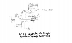
Sure! The H/K Cit. 5 is a superior implementation of Mullard style circuitry. Any 6L6GC "equivalent", including the 6П3С-Е, should be fine as the "finals". The 12BY7 is becoming scarce; so, I've provided a 6922 (6H23П-ЕB) cascode to take its place.
Thank you, I do not have any 6П3С-Е, just the regular 6П3С though.
As for the output transformer, in case of the 6L6 option, I was hoping to use this one.
- Status
- Not open for further replies.
- Home
- Amplifiers
- Tubes / Valves
- medium power (~20W) amplifier and power supply requirements