Am I missing something, it seems to me like we're discussing our different experiences.
BP - PEARL
BP - PEARL
M
Loudspeaker cabinets tend to have very high Q resonances and the usual attempts to correct that can move the resonances up in frequency but seldom reduce their effect.
Move a resonance up in frequency and there is less energy to excite the resonance. In a multiway if the resonances can be moved above the passband it is almost as if they don't exist.
dave
My recollection was that the KEF and the B&W were both very highly regarded.
We were selling KEF & B&W in the day... i foind the KEFs kinda lifeless, and they were better then the B&Ws. Spendors & Tangents had it all over them.
dave
Absolutely, this goes back to a paper by Peter Fryer. He found that every time you doubled Q the output had to be about 3dB louder for equal audibility. Now if we are talking a mechanical system and we double its Q, meaning we've cut frictional losses in half, output at resonance will go up by 6dB.
It becomes 3dB more discernable.
Toole's work had real people listening in controlled blind tests. Hi Q resonances were less dicernable.
dave
OK i have not read the Toole paper up to now and it would be interesting
how the setting was and how results can be interpreted.
From my own experience: Before my studies some buddies in
the neighbourhood towns asked me to develop a reasonable speaker,
so i choose to make a kit and let the guys build the cabinet on their own.
My job was then to make the crossover, and do the end tuning in
their homes. I varied the stuffing and the crossover characteristics
according to their specific rooms and listening positions.
It was a 2-way BR System with XO at 2.3 Khz.
Since each cabinet was manufactured in the taste of the "customers"
(of cause i charged them for the crossover, the speaker plans and the
service ...) i listened also to different cabinets although there were
recommendations from my side.
I heard that speaker in about 8 different rooms, which lead to a more
flexible crossover, taking all "seen" situations into account by switchable
components.
"Close reflecting side wall"
-> Downpadd tweeter in crossover region."
"Large listening distance in well damped room:
-> Compensate upper Midrange directivity of the (2) Bass-Midrangers
...
I built a "demonstration model" then, with had switchable crossover
and a cabinet that i regarded as well built. It was the heaviest damped
one.
The variants of the speaker were from
relatively light (but stiff) coreboard to
chipboard (MDF was not common that time) to
baltic birch plywood undamped and
baltic birch plywood damped heavily by 6mm of anti vibration mats on a 19mm wall.
Ranking from best to worst:
---------------------------
1.Birch Plywood damped
2.Birch Plywood undamped
3.Chippoard
4.Coreboard
What is hard to denote is the distance from Rank 1. to 2.
That distance is rather far ...
Rank 4 is what i would call an unusable speaker.
The Resonances were really disturbing and had relatively
high frequency.
I have got a chamber music recording for Cello and Contrabass:
Rank 4. wants me to leave the room, Rank 1. was a speaker
able to produce the timbre of the instruments in an enjoyful
manner.
In the years later i made cabinets to further improve that experience.
One good solution was a small bookshelf speaker in which i used
rather thin plywood to hold resonances low and used no wood glue
at all. The cabinet is from ovelerlapping sheets glued with 2mm gaps
filled wich an absorbent glue which is more plastic than silicone.
Braces are not going through but made of several sheets glued
together in that mentioned fashion.
It is one of the best cabinets i have built and it was the right decision
to make the walls relatively thin to hold resonant frequencies low and
apply a high amount of damping and decoupling.
That speaker works as a kind of "reference" in uncolored midrange,
it uses a small Visaton AL 130 up to 900 Hz and the crosses
over to a homebrew ribbon tweeter.
I use that speaker up to now sometimes when in doubt what my
current prototype does to the music ...
My Dipol 08 Design is the best lower midrange i had up to now and
the success is from damping, mass loading and avoidance of radiating
cabinet/baffle surface as far as possible.
I know that there is a couple of people convinced from
even undamped enclosures. AFAIK such an undamped fullrange
construction won a price in some contest lately ...
So there must be something to it - which some of us cannot follow.
Maybe there are two polar oppositions
resonant - clean
lifelike - lifeless
Maybe there are the "clean" (sonically!) preferring kind of people
who do not want to hear and feel resonances (from the speaker itself!).
Maybe there are "lifelike" people, which associate detail and
"bodily impact" with the feeling a low damped system produces.
What a vibrating sheet can do, is change the main direction of radiation
within a small frequency intervall, thereby producing some kind of
"additional diffuse sound field". That kind of sound field may be more
similar to the sound field of a piano e.g. than that of a speaker,
which is mainly a point source with a non diffuse sound field.
Since i seem to be more the "clean" type of listener i try to understand,
what it is, that the "lifelike" people regard as high.
Maybe i am a hidden "lifelike" person too, who knows ...
how the setting was and how results can be interpreted.
From my own experience: Before my studies some buddies in
the neighbourhood towns asked me to develop a reasonable speaker,
so i choose to make a kit and let the guys build the cabinet on their own.
My job was then to make the crossover, and do the end tuning in
their homes. I varied the stuffing and the crossover characteristics
according to their specific rooms and listening positions.
It was a 2-way BR System with XO at 2.3 Khz.
Since each cabinet was manufactured in the taste of the "customers"
(of cause i charged them for the crossover, the speaker plans and the
service ...) i listened also to different cabinets although there were
recommendations from my side.
I heard that speaker in about 8 different rooms, which lead to a more
flexible crossover, taking all "seen" situations into account by switchable
components.
"Close reflecting side wall"
-> Downpadd tweeter in crossover region."
"Large listening distance in well damped room:
-> Compensate upper Midrange directivity of the (2) Bass-Midrangers
...
I built a "demonstration model" then, with had switchable crossover
and a cabinet that i regarded as well built. It was the heaviest damped
one.
The variants of the speaker were from
relatively light (but stiff) coreboard to
chipboard (MDF was not common that time) to
baltic birch plywood undamped and
baltic birch plywood damped heavily by 6mm of anti vibration mats on a 19mm wall.
Ranking from best to worst:
---------------------------
1.Birch Plywood damped
2.Birch Plywood undamped
3.Chippoard
4.Coreboard
What is hard to denote is the distance from Rank 1. to 2.
That distance is rather far ...
Rank 4 is what i would call an unusable speaker.
The Resonances were really disturbing and had relatively
high frequency.
I have got a chamber music recording for Cello and Contrabass:
Rank 4. wants me to leave the room, Rank 1. was a speaker
able to produce the timbre of the instruments in an enjoyful
manner.
In the years later i made cabinets to further improve that experience.
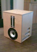
One good solution was a small bookshelf speaker in which i used
rather thin plywood to hold resonances low and used no wood glue
at all. The cabinet is from ovelerlapping sheets glued with 2mm gaps
filled wich an absorbent glue which is more plastic than silicone.
Braces are not going through but made of several sheets glued
together in that mentioned fashion.
It is one of the best cabinets i have built and it was the right decision
to make the walls relatively thin to hold resonant frequencies low and
apply a high amount of damping and decoupling.
That speaker works as a kind of "reference" in uncolored midrange,
it uses a small Visaton AL 130 up to 900 Hz and the crosses
over to a homebrew ribbon tweeter.
I use that speaker up to now sometimes when in doubt what my
current prototype does to the music ...
My Dipol 08 Design is the best lower midrange i had up to now and
the success is from damping, mass loading and avoidance of radiating
cabinet/baffle surface as far as possible.
I know that there is a couple of people convinced from
even undamped enclosures. AFAIK such an undamped fullrange
construction won a price in some contest lately ...
So there must be something to it - which some of us cannot follow.
Maybe there are two polar oppositions
resonant - clean
lifelike - lifeless
Maybe there are the "clean" (sonically!) preferring kind of people
who do not want to hear and feel resonances (from the speaker itself!).
Maybe there are "lifelike" people, which associate detail and
"bodily impact" with the feeling a low damped system produces.
What a vibrating sheet can do, is change the main direction of radiation
within a small frequency intervall, thereby producing some kind of
"additional diffuse sound field". That kind of sound field may be more
similar to the sound field of a piano e.g. than that of a speaker,
which is mainly a point source with a non diffuse sound field.
Since i seem to be more the "clean" type of listener i try to understand,
what it is, that the "lifelike" people regard as high.
Maybe i am a hidden "lifelike" person too, who knows ...
Toole's work had real people listening in controlled blind tests. Hi Q resonances were less dicernable.
dave
Toole quotes the previous work of Fryer and repeats his conclusions. Both used real people and listening tests, as you would have to in tests of perceptual thresholds.
The basic test is to have a flat signal path and a 2nd parallel path through a parametric equalizer type resonance (second order bandpass). With the resonant circuit you can adjust frequency and Q. At the same time you can set how much of the resonance to mix in with the "flat" signal: dilution. Usually the level is set such that it is at or below the level of the same frequency in the flat arm. As such it will put a barely visible wiggle in the flat response.
The test is to vary the Q and then raise the resonance level until it is just perceived. As you stated they found that doubling the Q made the threshold 3dB higher. (The resonance level had to be 3dB louder to be perceived.) As I stated, with a mechanical system if you double the Q by cutting frictional losses the level at resonance will naturally rise 6dB, making it more audible by the 3dB excess over the 3dB threshold rise.
David
Hi:
...
- the decoupling compliance and the decoupled mass set up a 'Q-y' mechanical tank that sounds like hell ...
...
If there is a misalignment in the decoupling resonator
(mass/spring/resistance dimensioning) e.g.
- resonant frequency too high (within usable bass range of speaker)
- Q too high
i can follow that for sure.
When conventionally mounted, the mass of the driver can be seen as
a 6db/octave lowpass filter for the resulting velocity at the cabinet
mounting point:
Assumed that the driving force from the voice coil is frequency
independent, the velocity at the mounting point between driver
and cabinet will be half, if frequency is doubled.
This assumes further the driver's basket beeing a rigid mass and the
bending cabinet walls beeing a resistive load at the contact point
(which is not the case, since this is for simplification).
Introducing a spring now between driver basket and cabinet
mounting point, means the velocity of the driver's basket to be
clamped across both terminals of the spring.
The spring will react as follows:
If the frequency of the alternating velocity across the spring is
doubled, the force through the spring is half.
This adds another 6db/octave.
Mass loading alone can lower the resonance and the driving force
into the cabinet mounting point.
But the lowpass for the force acting on the cabinet stays 6db/octave.
The additional spring makes up a 12db/octave lowpass.
This is useful since a 6db/octave is not steep enough to
compensate for 2 nasty effects, we have to deal with:
1. Radiation from the cabinet walls getting more effective with frequency
when rising towards the coincidence frequency of the walls, where the
propagation velocity of bending waves becomes equal to the propagation
velocity in air.
2. The rising sensitivity of the ear in the bass to midrange and
thus coloration and uneven frequency response getting more relevant in
the mid frequencies.
...
- decoupled from the box or not the drive unit's acoustic output is more than sufficient to strike the high-Q box panel resonances into full essentially full 'song.'
...
This holds for sure in a closed cabinet, especially when stuffed only lightly.
Since i am often working with open baffles in the last time, the excitaton from
cabinet pressurization and box resonances does not play a role then.
Direct mechanical coupling and difference in alternating pressure on both sides of
the baffle are the predominant effects there, which cause vibration of the baffle.
Kind Regards
The test is to vary the Q and then raise the resonance level until it is just perceived. As you stated they found that doubling the Q made the threshold 3dB higher. (The resonance level had to be 3dB louder to be perceived.) As I stated, with a mechanical system if you double the Q by cutting frictional losses the level at resonance will naturally rise 6dB, making it more audible by the 3dB excess over the 3dB threshold rise.
David
Just to understand:
Everytime the Q was doubled, the resonant signal path was
padded down by 6db (=start level) to give the resonant
frequency about the same level as in the flat signal path ?
Then the level of the resonant path was rised until a difference
- resonant quality - was audible.
The least noticeable difference in level which made the resonant path
audible, turned out do be 3db higher than it was with the setting having
half the Q.
Since in both settings the least noticeable level difference was
measured relative to the s t a r t i n g level of the resonant arm,
which was 6db lower for Qx2, the Qx2 aligned resonant arm is audible
at a level of -3db relative to the Qx1 arm.
Right ?
-----
Given i picked that right, conclusion would be clearly that high Q
resonances are audible even at lower levels of excitation.
When the Qx2 resonance gets audible, then truly the resonant peak is
3 db higher than in the Qx1 case.
But it does not make sense to compare the peaks, the exciting levels
for the "just noticeabe difference" found in the experiment are
of interest.
The two signal paths could be set in analogy to two differently
prepared walls of a speaker cabinet say one with fs=100 Q=10 and
the other with same fs and Q=20.
Given these would be the only resonances of the cabinet
for simplification, the excitation of the Q=20 wall would have
to be reduced by 3db to not degrade the quality of the cabinet.
That would be a concludent application of the cited auditory finding
to cabinet design.
The fact found that the peak of the Qx2 system may lurk 3db higher
at fs over the neutral level than the Qx1 system, may rise speculation
if the area under the peak is of perceptual interest:
Around fs the high Q peak is allowed to lurk higher, probably - yes -
because it is more narrow banded.
But the area under a resonance curve is always larger for the higher
Q system. Sad but true.
In the years later i made cabinets to further improve that experience.
One good solution was a small bookshelf speaker in which i used
rather thin plywood to hold resonances low and used no wood glue
at all. The cabinet is from ovelerlapping sheets glued with 2mm gaps
filled wich an absorbent glue which is more plastic than silicone.
Braces are not going through but made of several sheets glued
together in that mentioned fashion.
It is one of the best cabinets i have built and it was the right decision
to make the walls relatively thin to hold resonant frequencies low and
apply a high amount of damping and decoupling.
Hello, do you have any photos of this construction? What kind of "absorbent" glue did you use? And why not simply use sand between the two walls? Thanks.
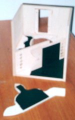
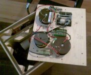
That where real photos on paper from mounting i made about 2003.
I used my handy now to copy the photo ... may be sufficient to get an idea.
That cab is rather complex, there is a wedge shaped chamber for
the ribbon tweeter because the ribbon is back open.
The main chamber consists of two cascaded helmholtz resonators,
not relevant for our discussion on damping ...
but you see the inner port with holes at the ends and some kind
of K-Slot to suppress resonances of the inner port.
The holes in the port were closed then - not needed AFAIR.
The 2nd port going outside is not visible in that step of mounting.
I used "Pattex Super Montage Extreme" it was ebony colored that time,
i think they changed it into transparent by now.
To hold the gaps on distance i used chips from cork where necessary,
they were removed afterwards where possible.
The glue needs larger surface than wood glue, but you need
surface anyway to get the damping effect.
The curved bracing is to get larger gap surface and to use
shear forces on the damping layer.
The divider for the tweeter compartment e.g. is not
directly glued to the side walls, but damped fixed to some
bars.
Why not sand ? Surely sand is nice but i think you wont get away
with less than 4cm thickness of the walls in a bookshelf speaker ...
in wanted to make a compact speaker.
The speaker is ridiculously complex ... that's why i gave up further
devopment, but the cabinet works very well especially concerning
vibrational damping.
Kind Regards
Attachments

Last edited:
Just to understand:
Everytime the Q was doubled, the resonant signal path was
padded down by 6db (=start level) to give the resonant
frequency about the same level as in the flat signal path ?
Then the level of the resonant path was rised until a difference
- resonant quality - was audible.
The least noticeable difference in level which made the resonant path
audible, turned out do be 3db higher than it was with the setting having
half the Q.
Since in both settings the least noticeable level difference was
measured relative to the s t a r t i n g level of the resonant arm,
which was 6db lower for Qx2, the Qx2 aligned resonant arm is audible
at a level of -3db relative to the Qx1 arm.
Right ?
Essentially right. I believe every time you change the Q (raise the Q) you would start over with the side chain at a low level and raise until it was audible. (JND: just noticable difference type test.) The 6dB or 3dB realtionships wouldn't be obvious until you analyzed the results and you wouldn't want to prejudice the test by always resetting the level the "right" amount.
With a parametric EQ you can set the variables such that turning the "Q" control varies bandwidth and has no impact on center frequency level. With mechanical systems this is not the case, varying Q strongly impacts level at resonance (level at resonance approx. = 20 log Q).
Higher Q is less audible but with mechanical systems modifying Q impacts resonance level at twice the rate necessary. This is a good result otherwise Q reduction, i.e. damping cabinets, wouldn't help us out, would it? We would want our cabinet resonances to be as strong as possible because their narrowness would make them innaudible.
Experience tells us that is not the case.
David
...
I used "Pattex Super Montage Extreme" it was ebony colored that time,
i think they changed it into transparent by now.
...
meant "ivory" not ebony , mistake comes from the song "ebony & ivory"
...
We would want our cabinet resonances to be as strong as possible because their narrowness would make them innaudible.
Experience tells us that is not the case.
David
That meets my experience too. Thank you for clarification of the
test setting David !
I'd like to get the papers from Fryer / Toole into hands sometime.
What do you think about the 1. order vs. 2. order filter model
concerning driver decoupling, was a bit snapshot i must admit ...
That meets my experience too. Thank you for clarification of the
test setting David !
I'd like to get the papers from Fryer / Toole into hands sometime.
What do you think about the 1. order vs. 2. order filter model
concerning driver decoupling, was a bit snapshot i must admit ...
I'll have to think about the 6dB per part but a decoupled mass (the woofer) is definitely a 2nd order system (12dB per octave decoupling). The losses, resistance or friction in the compliant bits, will generally keep the Q down and may tend to degenerate the decoupling towards 1st order if they are high enough. Mass of the woofer (assuming cabinet mass is much higher) and the compliance determine the resonance frequency of the assembly. Above that frequency velocity (or acceleration) fall off 12 dB/octave. Below that they are the same.
Search the web for decoupled counterweights (tonearms or even turntable suspensions). An interesting application is the seismic counterweights used for skyscrapers for earthquake control. The biggest Dual tonearm counterweight you ever saw!
I might be able to find a copy of the Fryer paper over the weekend.
A correction of something I said earlier: this is not a JND (just noticeable difference test) but a threshold of perception test.😀
David
interesting discussion gentlemen, thank You!
thanks God when one chooses to have a driver on top of a small enclosure, not necessarily cylindrical, nevertheless Yoshii-san's way in a broad sense - it all becomes so much easier
BTW long way from Onkyo Grand Scepter's 117 kg to 9 kg of Yoshii 9, both on picture below
thanks God when one chooses to have a driver on top of a small enclosure, not necessarily cylindrical, nevertheless Yoshii-san's way in a broad sense - it all becomes so much easier
BTW long way from Onkyo Grand Scepter's 117 kg to 9 kg of Yoshii 9, both on picture below
Attachments
Why not sand ? Surely sand is nice but i think you wont get away
with less than 4cm thickness of the walls in a bookshelf speaker ...
in wanted to make a compact speaker.
The speaker is ridiculously complex ... that's why i gave up further
devopment, but the cabinet works very well especially concerning
vibrational damping.
Kind Regards
Hello, thanks for the photos and further explanation. Just to clarify, rather than "move" the resonances out of the speaker's passband, you chose to incorporate and make friendly resonances within the passband(?). I'm planning to build a new cabinet with sand, but my goal was to convert the resonances into heat. I've built a mass loaded cabinet but something seemed amiss with a "dead" sound. I like the creativity of your box (light and compact), but I don't know a method to predict what frequency(s) the box will resonate. Perhaps, the original idea in this post, to decouple the speaker driver from the box needs to be further investigated. Specifically, exactly how to implement the decoupling.
...
Just to clarify, rather than "move" the resonances out of the speaker's passband, you chose to incorporate and make friendly resonances within the passband(?).
...
Yes "friendly" resonances by keeping frequencies low and the Qs also ...
In a subwoofer the "move resonances above the passband" by stiffness
is a way to go. In a 2-Way with fs > 1000 Hz nearly impossible.
I heard a small cabinet from casted aluminium with very
thick walls and ribs in it. It was is made of two halves with
a damping glue inbetween.
That was working good, even for fullrange. It seemed to have
stiffness, diffusivity, damping. "Knuckle wrap test " was really
impressing, no "ping" or "pong" like the material would suggest.
The Manufacturer said it was also because of "special additives" ... 😉
OK but that kind of "Sand Casting" is expensive.
"Voicepoint" Speaker:
HiFi Heimkino Audio Guide
------
Sand filled enclosures are highly regarded, so if you have the space
and the recommended fork lifter ... 😀
One design issue might be a good driver cutout in the thick baffle,
giving as free space as possible behind the cone. When the baffle
is 4-6cm in thickness, the baffle cutout should be conical to
avoid the risk of building a helmholtz resonator behind the driver.
Basket, magnet and baffle may close a great percentage of the
cone area, thereby enclosing an air volume, which is able ro
resonate.
I might be able to find a copy of the Fryer paper over the weekend.
I would love to see a copy of that if you find it.
dave
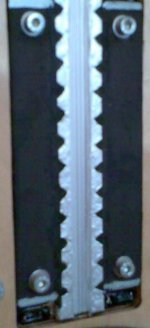
I've done a lot of mounting methods over the years. My current bass cabinets have a planned constrained layer damping. A beveled (low diffraction) ring of BB ply is prepared, and is clamped with professional grille retainers, like these:
Parts-Express.com😛enn-Elcom G0780KIT Large Grill Clamp Kit | grill clamp speaker grill mesh grill metal grill grille speaker cover
Gasketing is done in various ways. All my intended drivers have front gaskets, so they're pretty much taken care of. The back end is also gasketed using a soft foam tape or the like, as is the side edge of the frame. The driver is largely flush mounted with the baffle plane to help keep it in place.
I believe this will do a solid job of reducing energy transfer into the baffle while minimizing standing energy in the frame. I've used a similar system on my open baffles to great success. One needn't use the wood ring if not desired, the heavy duty metal grilles from P.E. would do the job too, if you're not concerned with getting much highs from your 10s, 12"s, and 15"s for which this is appropriate. For smaller driver sizes, the wooden ring begins to present a significant modification of the wavefront.
Parts-Express.com😛enn-Elcom G0780KIT Large Grill Clamp Kit | grill clamp speaker grill mesh grill metal grill grille speaker cover
An externally hosted image should be here but it was not working when we last tested it.
Gasketing is done in various ways. All my intended drivers have front gaskets, so they're pretty much taken care of. The back end is also gasketed using a soft foam tape or the like, as is the side edge of the frame. The driver is largely flush mounted with the baffle plane to help keep it in place.
I believe this will do a solid job of reducing energy transfer into the baffle while minimizing standing energy in the frame. I've used a similar system on my open baffles to great success. One needn't use the wood ring if not desired, the heavy duty metal grilles from P.E. would do the job too, if you're not concerned with getting much highs from your 10s, 12"s, and 15"s for which this is appropriate. For smaller driver sizes, the wooden ring begins to present a significant modification of the wavefront.
- Status
- Not open for further replies.
- Home
- Loudspeakers
- Full Range
- Mechanical isolation of driver from cabinet